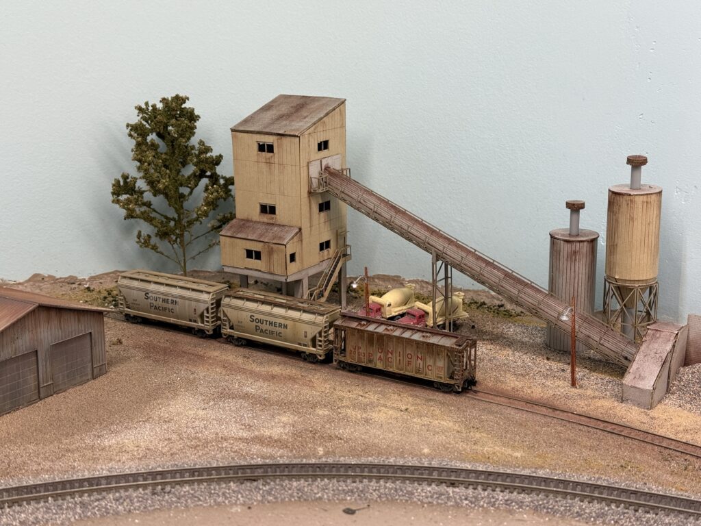
Ready-mix Cement Plant
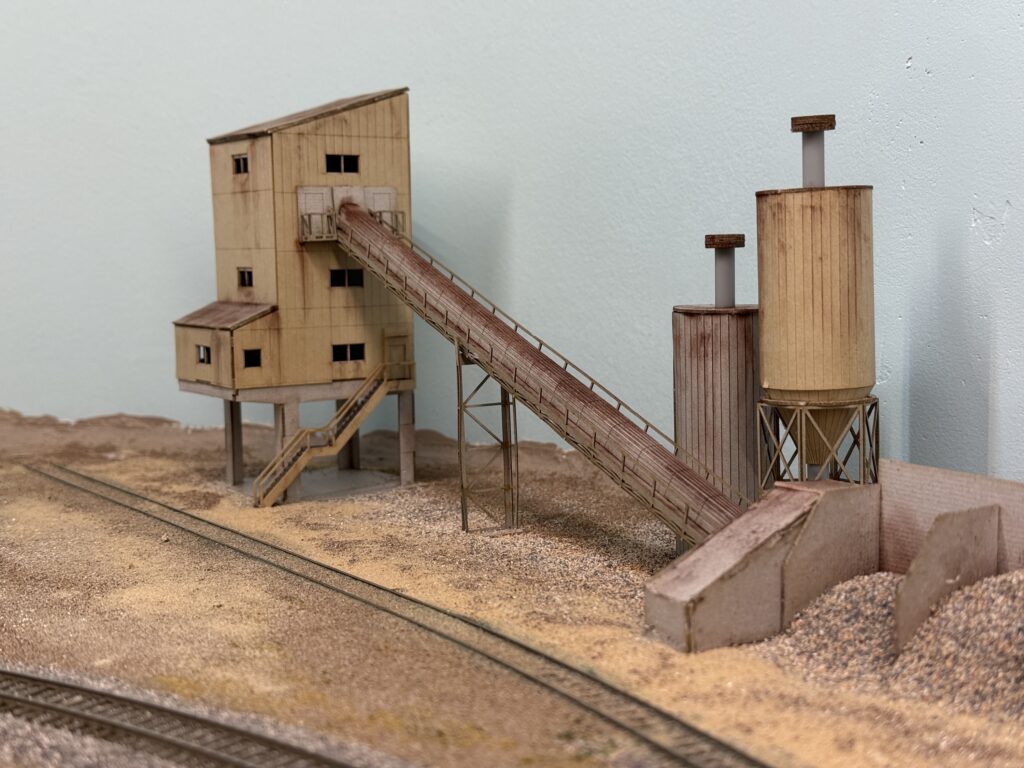
After installing the bridge, I placed the ConRock Ready-Mix Cement Plant
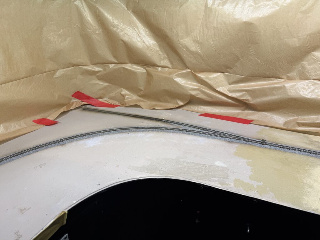
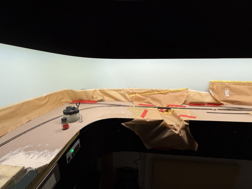
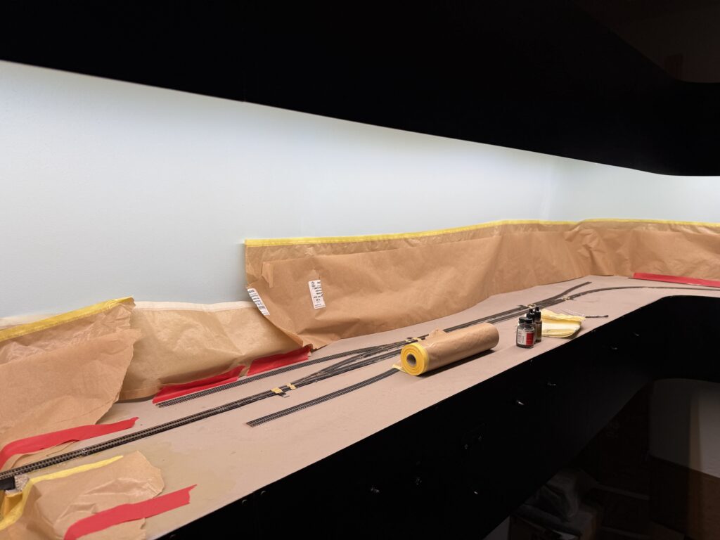
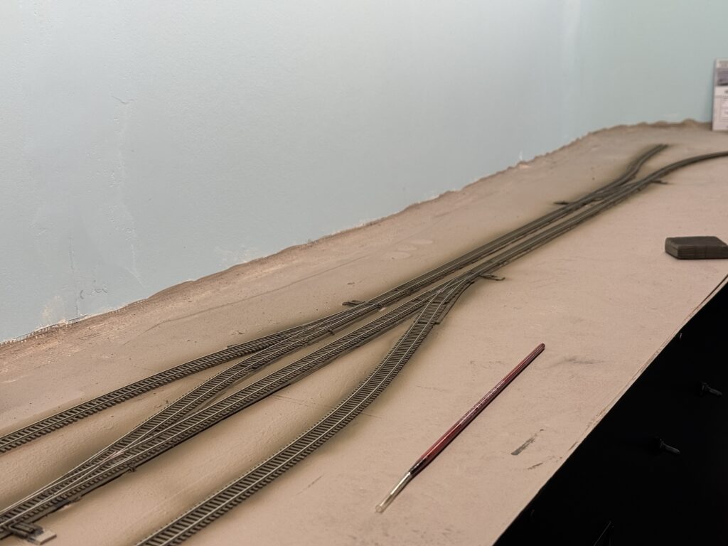
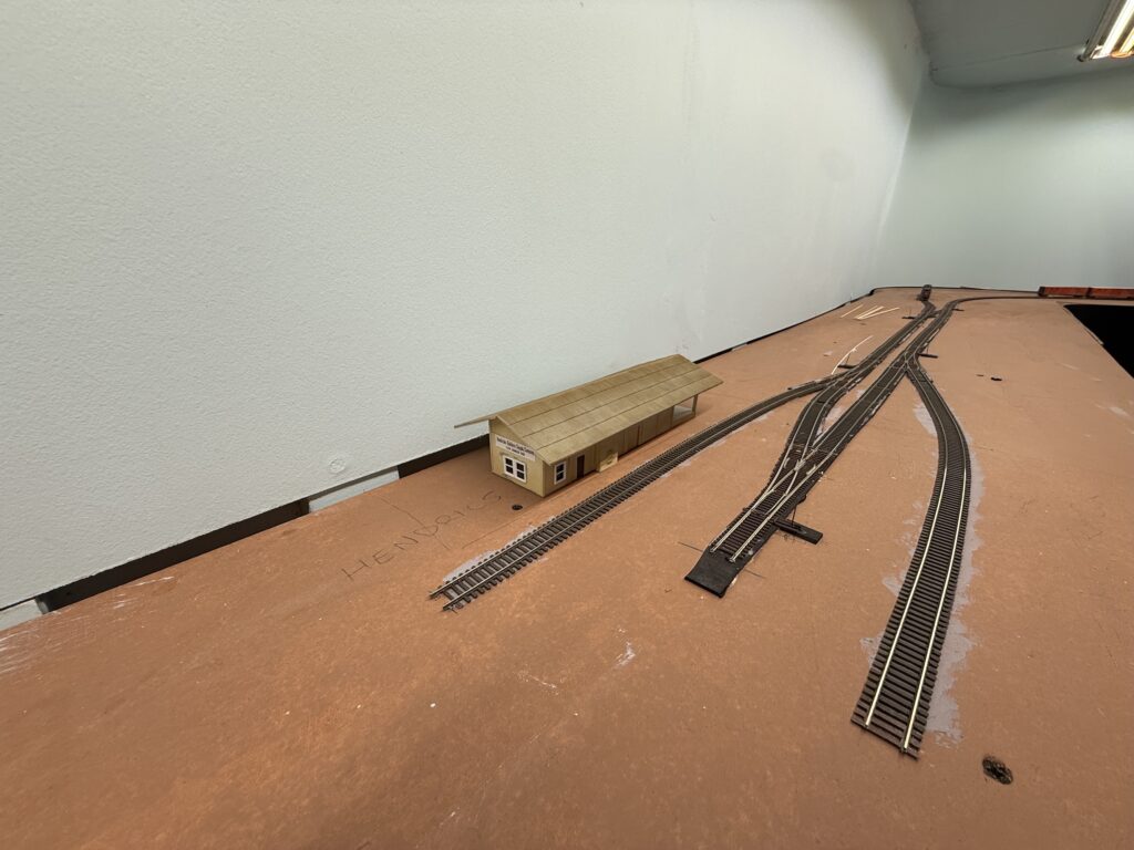
The layout corner where the ConRock Ready-Mix Cement Plant is located will be the first area to receive scenery.
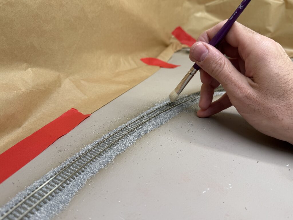
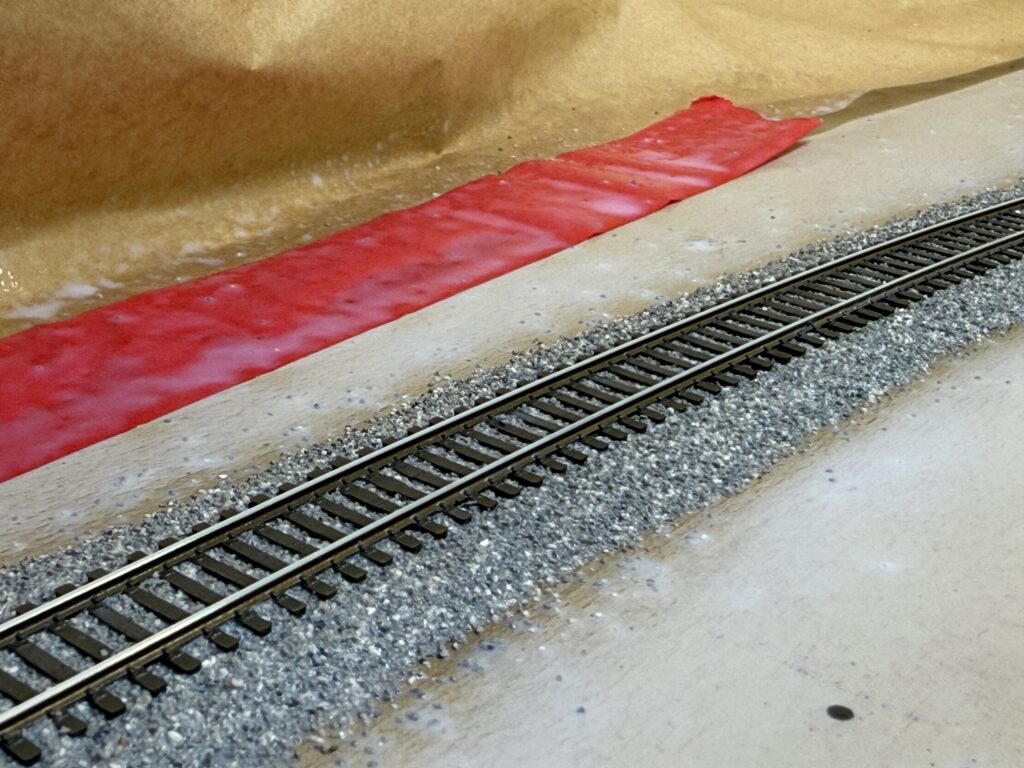
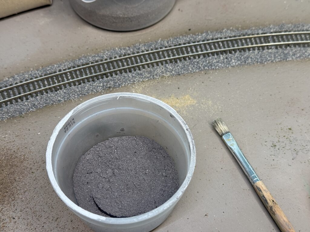
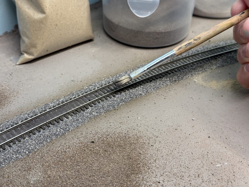
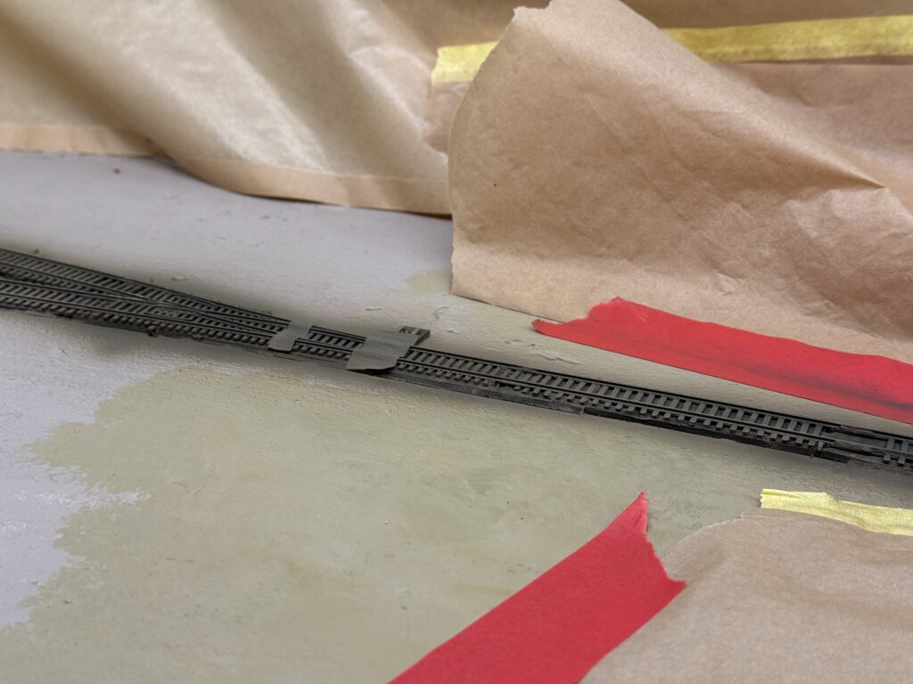
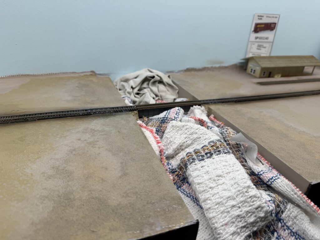
I added rough terrain texture near the bridge and ballasted the first section of track. To protect the bridge scene, I laid a couple of towels over the riverbed.
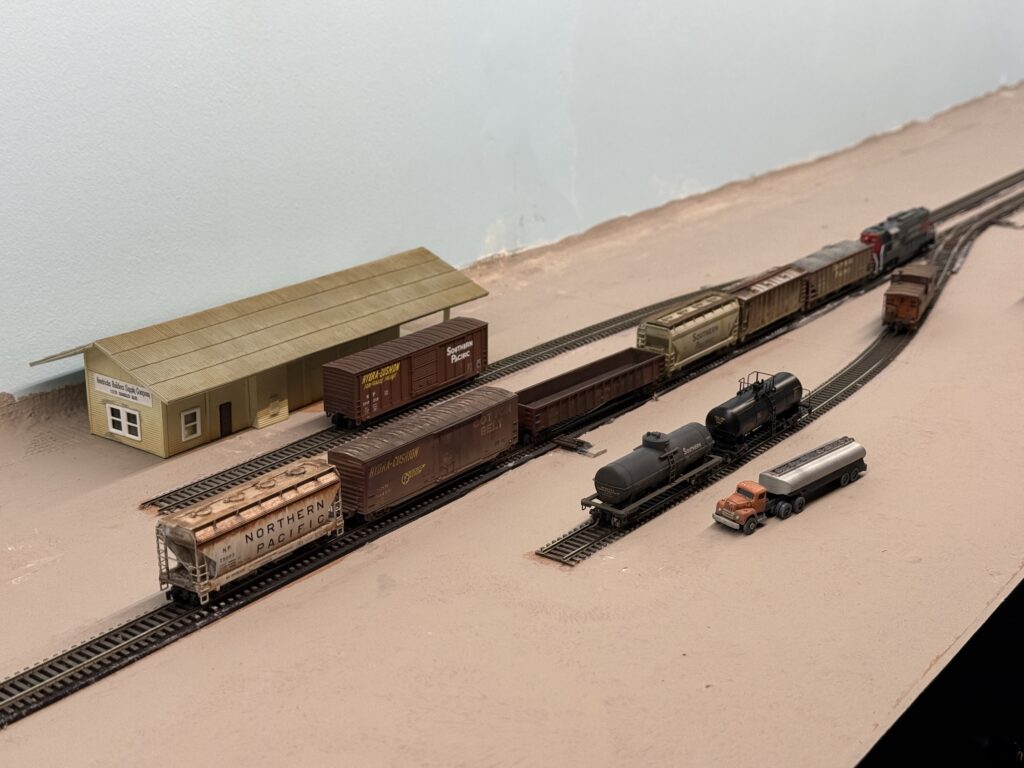
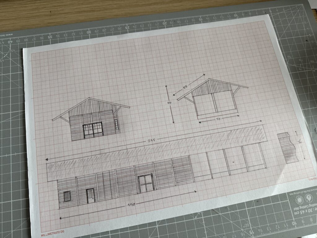
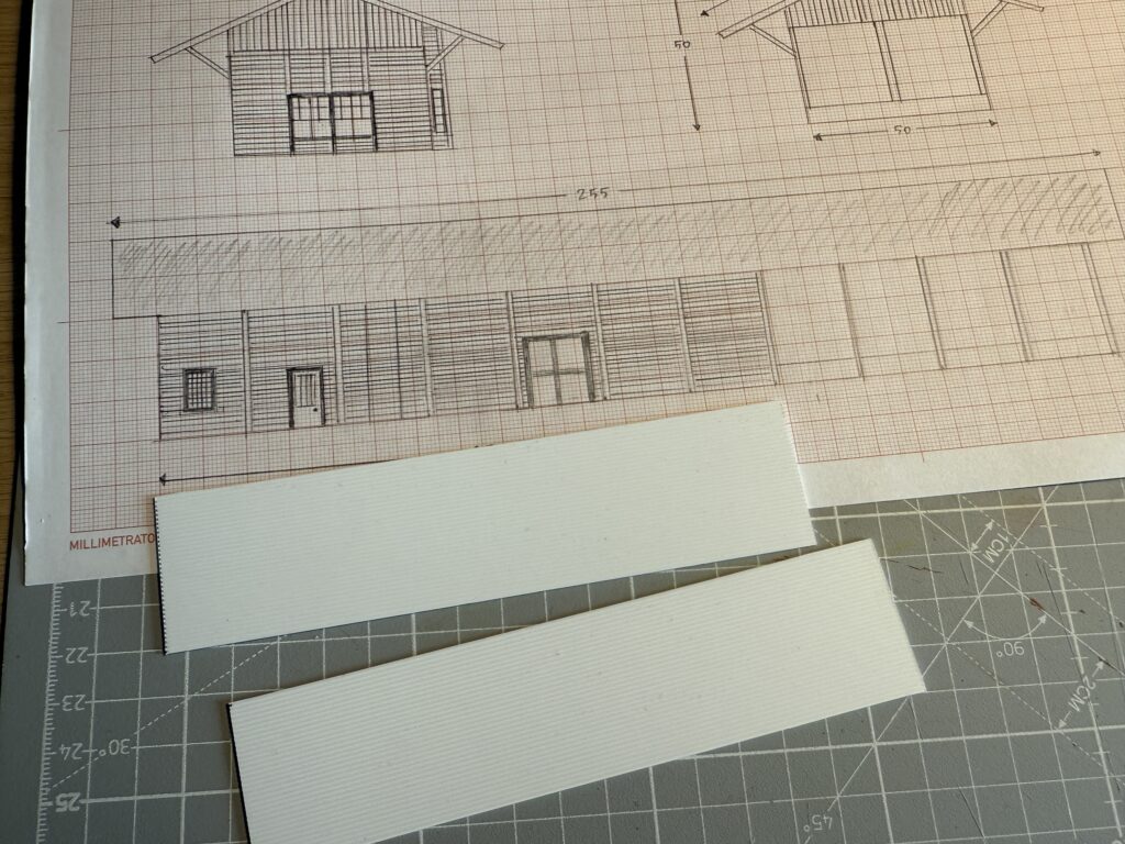
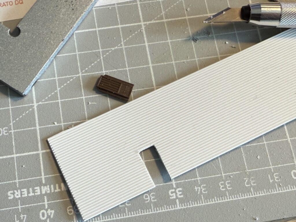
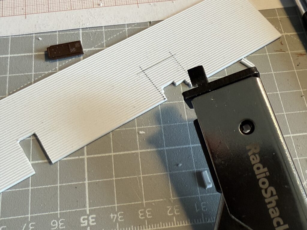
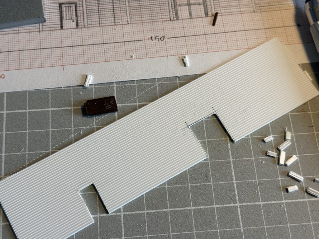
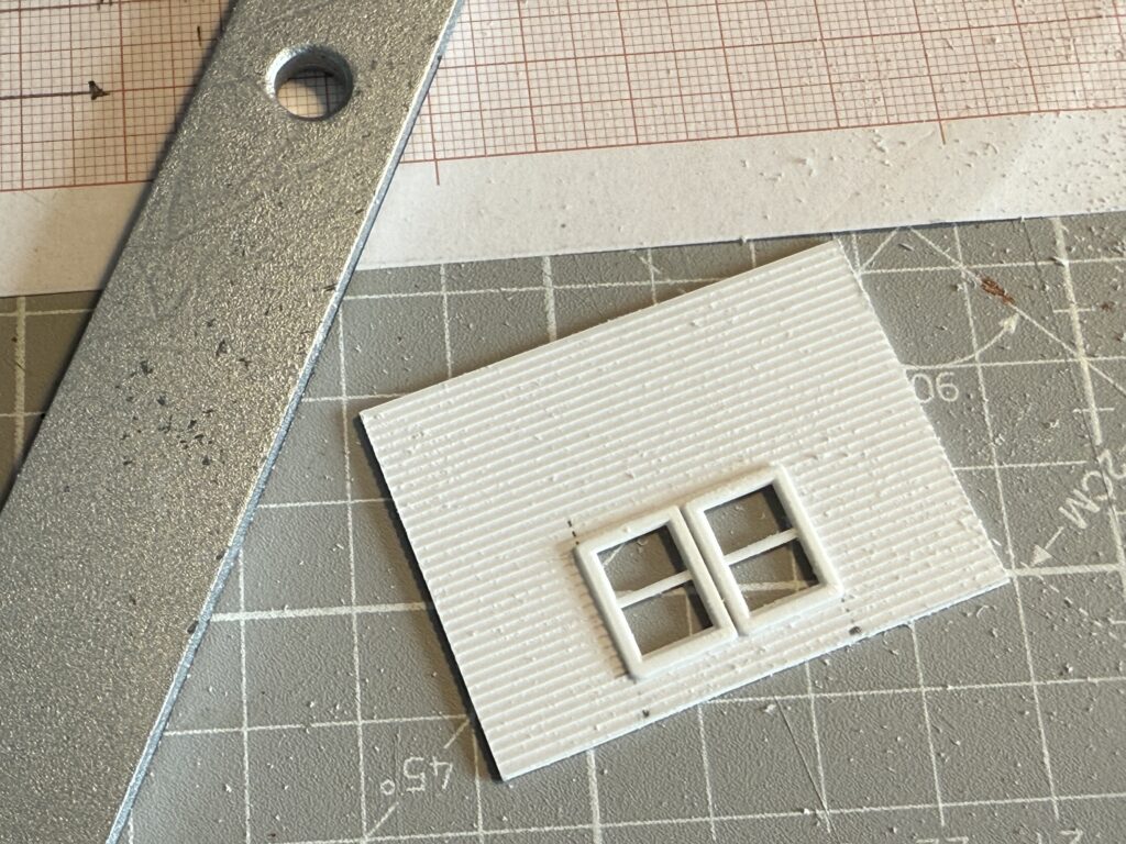
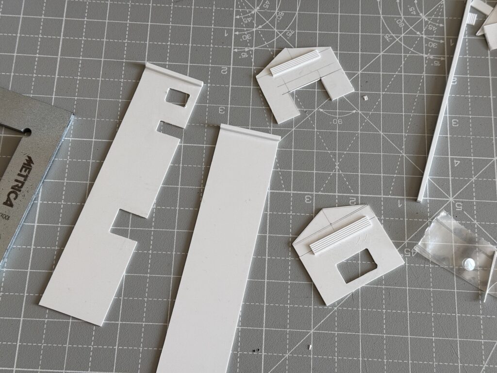
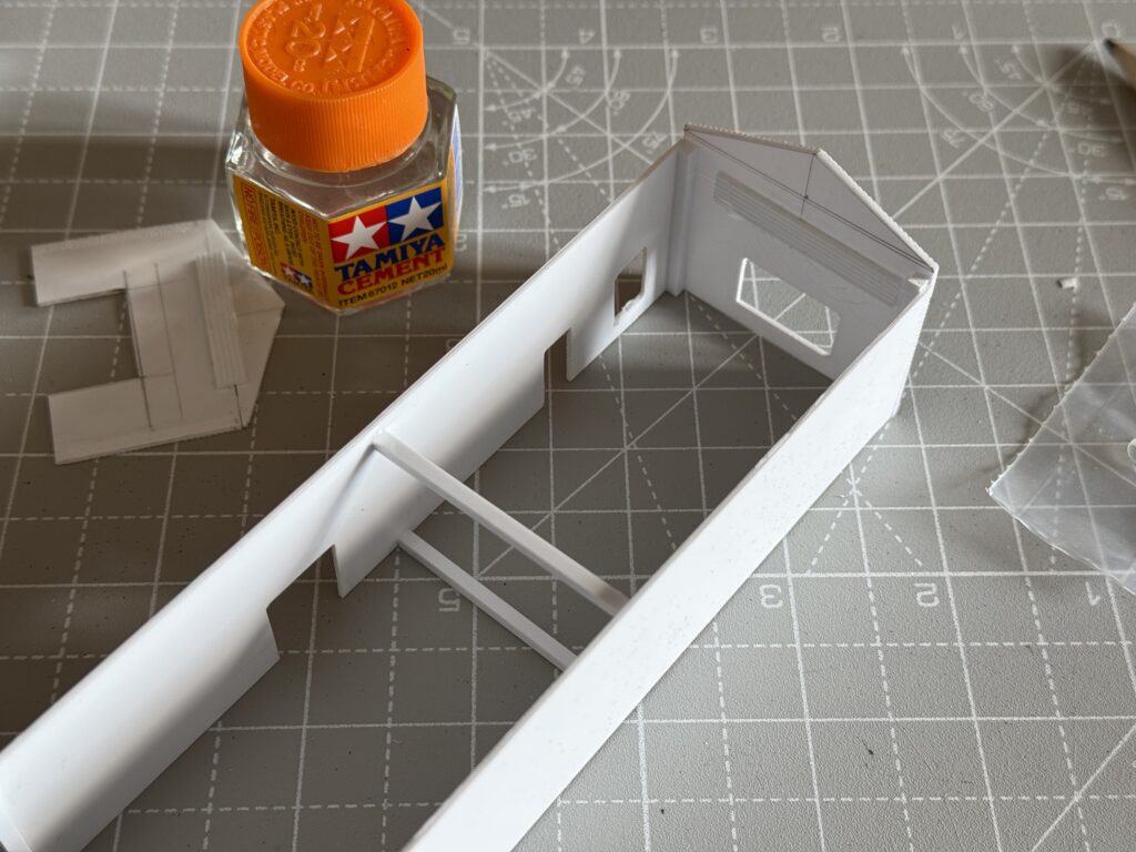
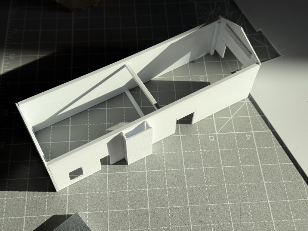
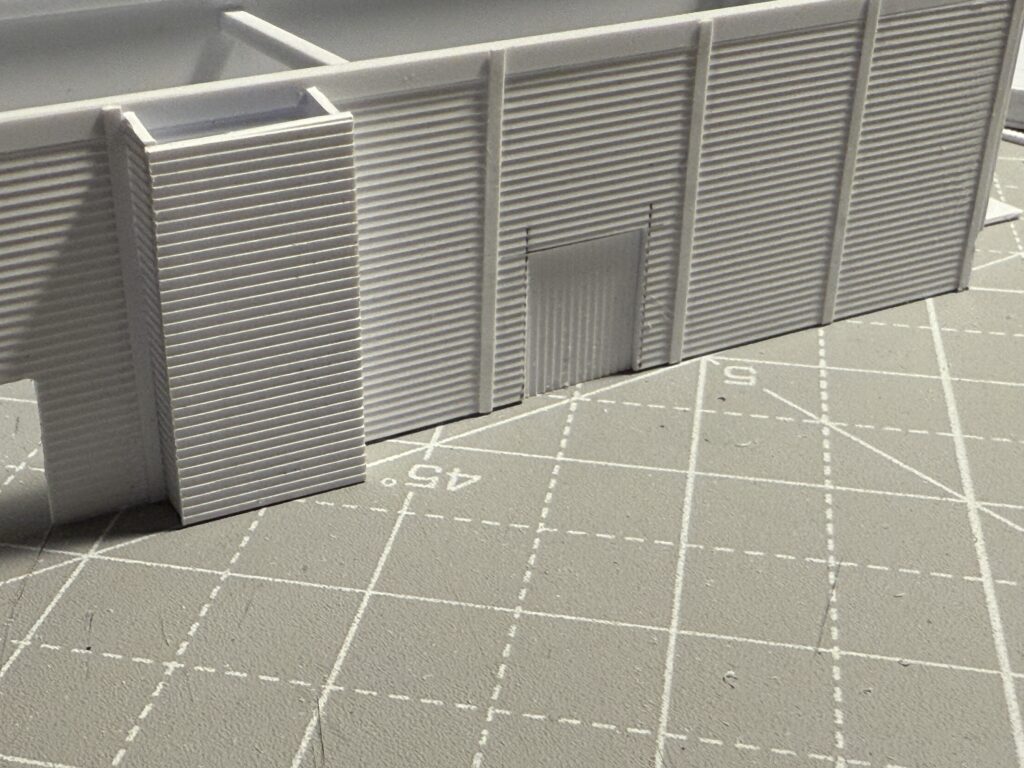
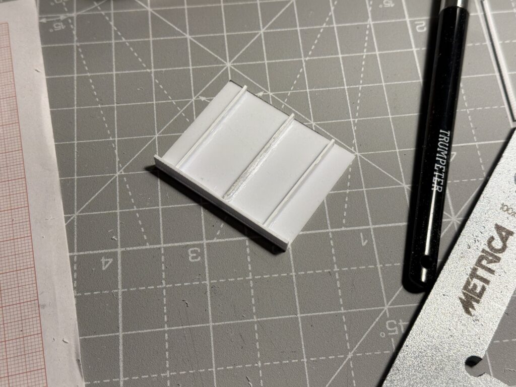
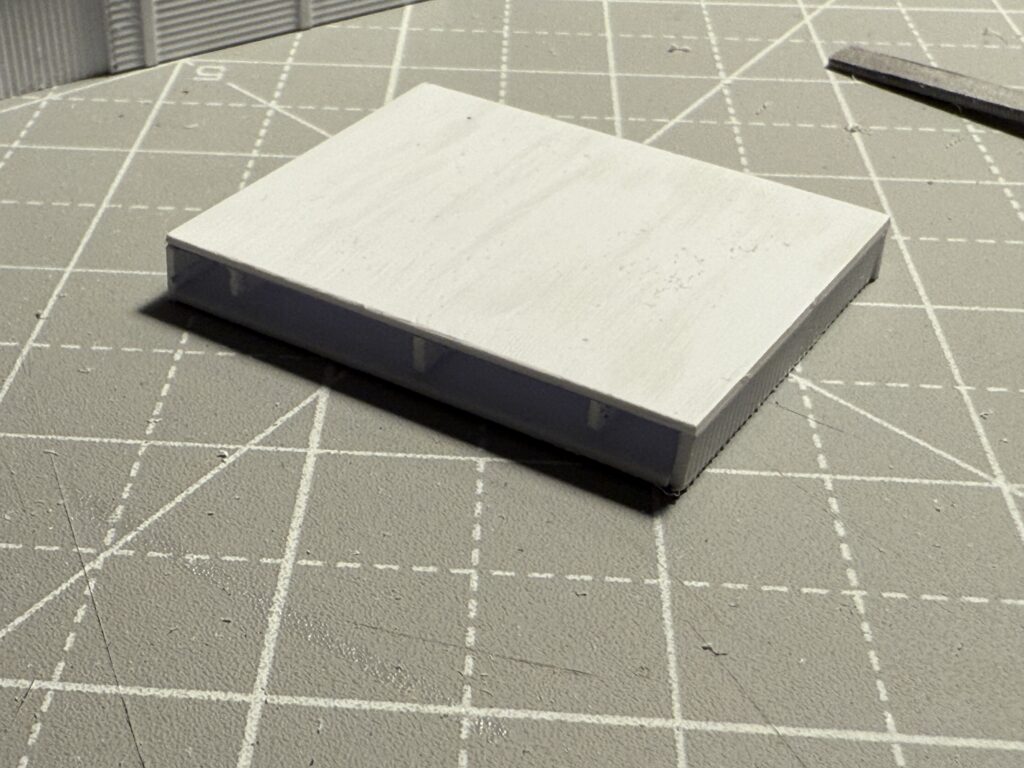
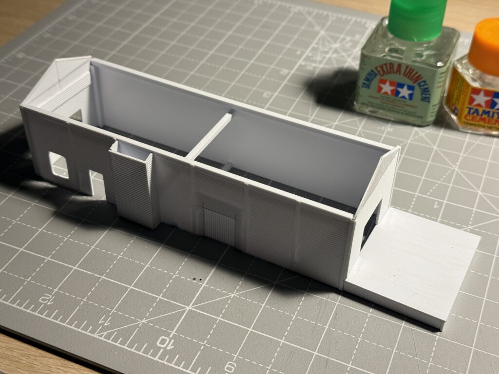
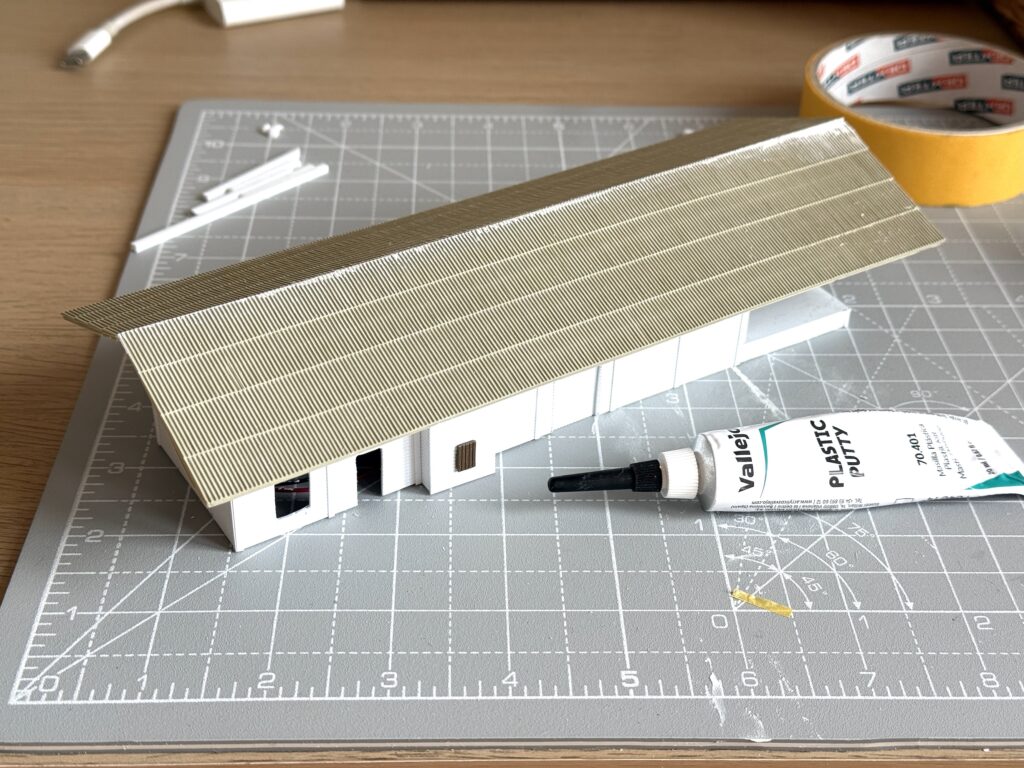
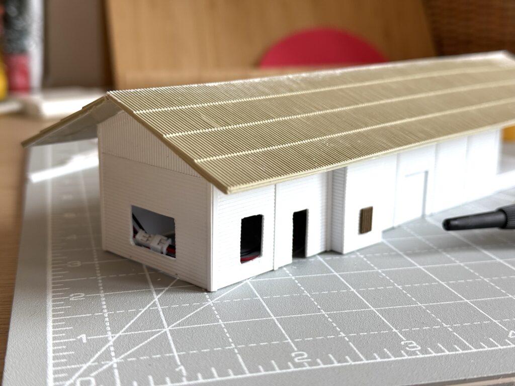
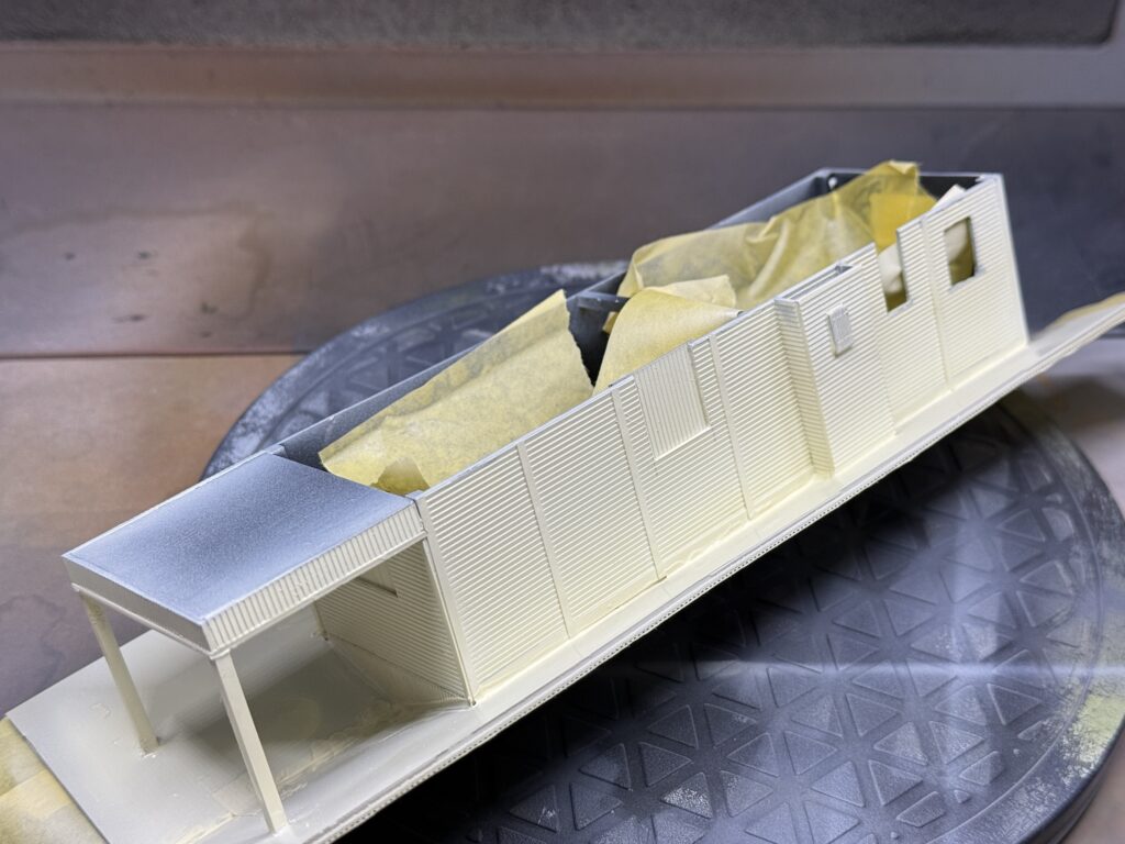
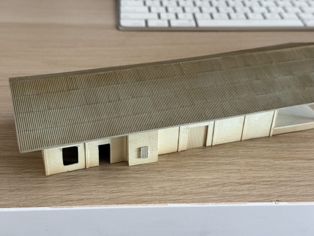
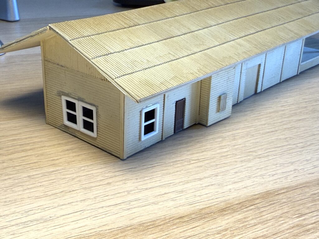
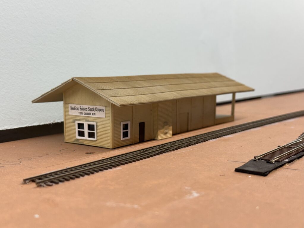
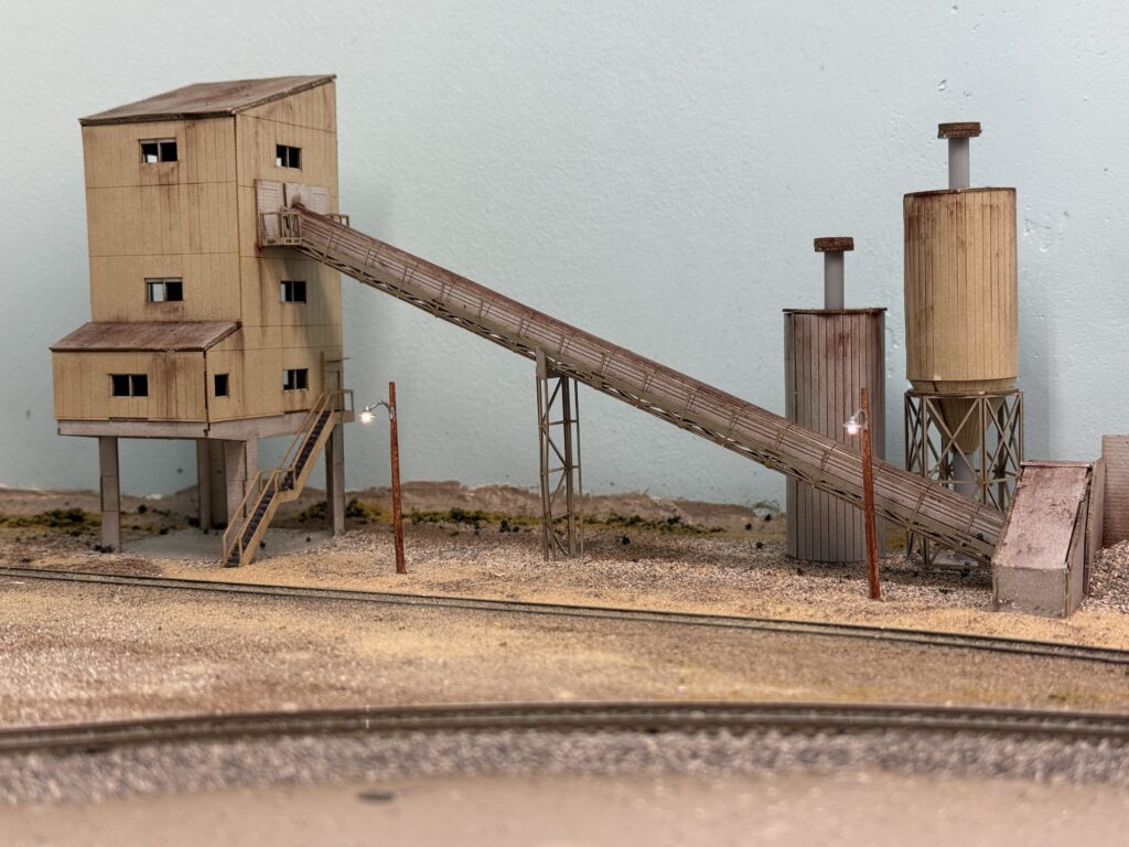
Then, I installed the cement plant structure. The building is a Japanese laser-cut paper kit that fits my needs perfectly.
The kit is made by a Japanese brand called Advance. It is a 1:150 scale model, but it still looks very good and fits the scene nicely.
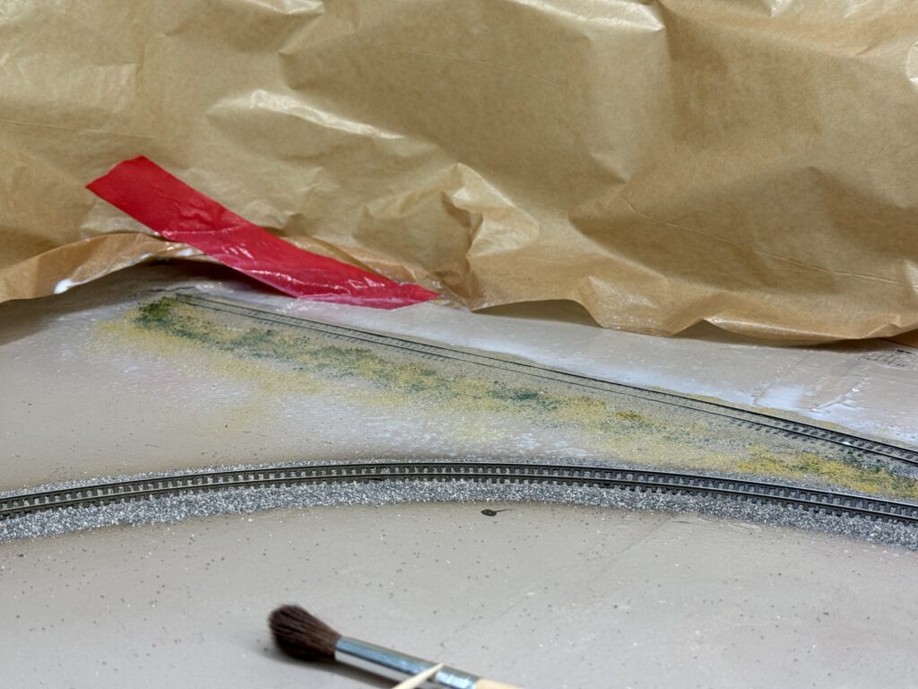
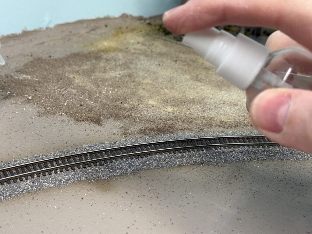
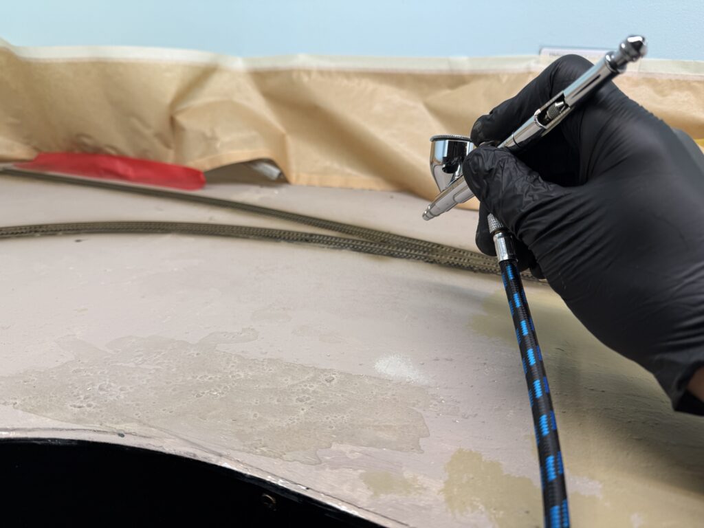
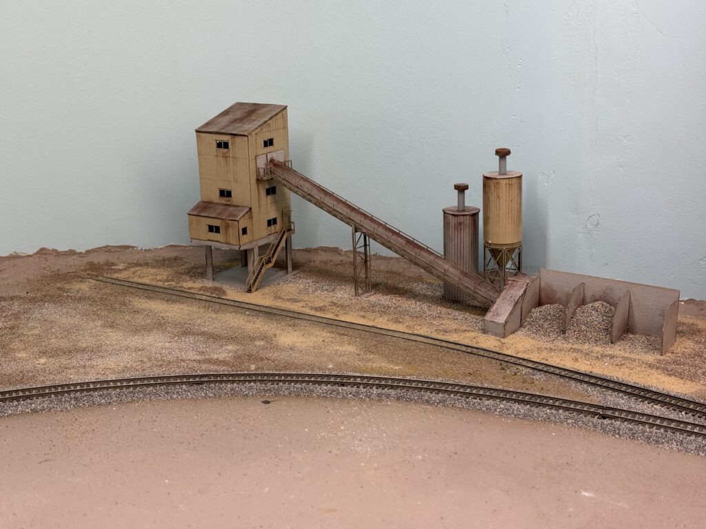
I first sprayed a 50:50 mix of alcohol and water to reduce surface tension. Then, I sprinkled on some terrain powders and followed up with a 50:50 mix of matte medium and water.
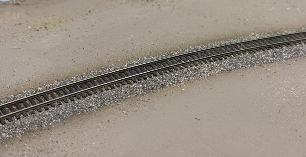
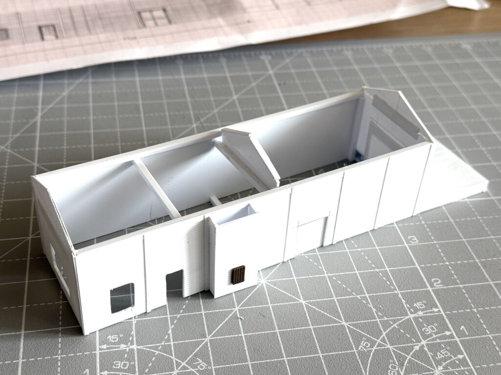
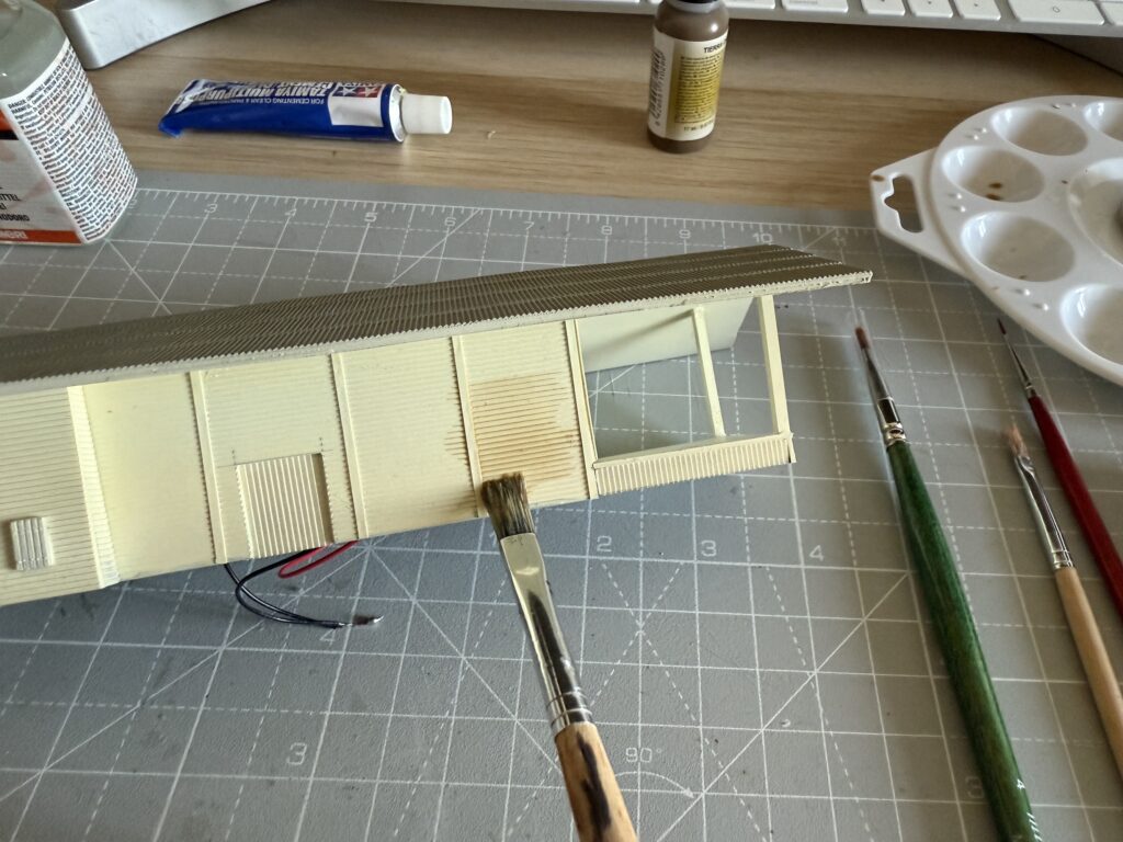
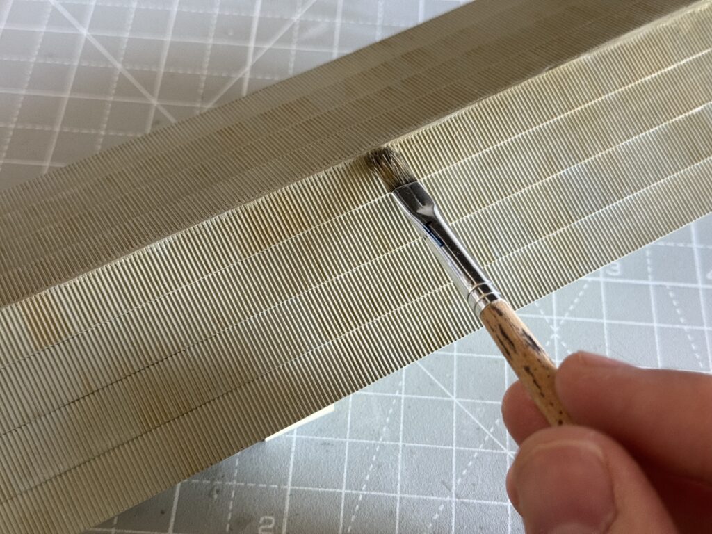
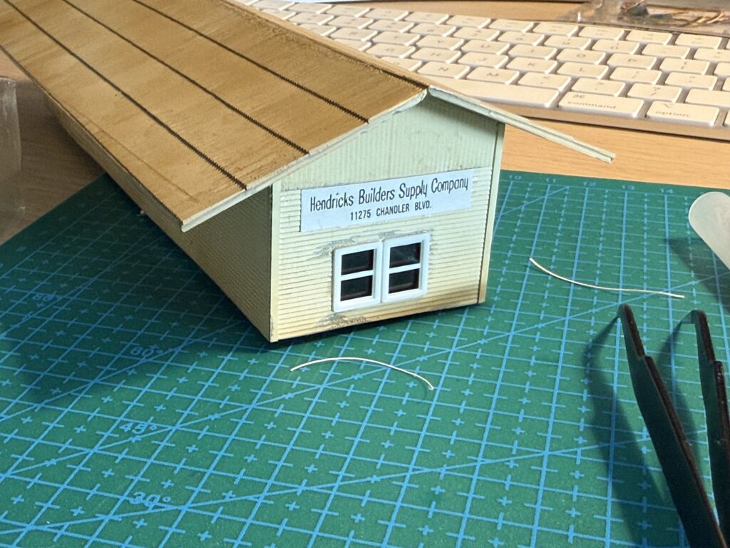
The kit was weathered with powdered pigments, and the surrounding terrain was glued in place using Liquitex Matte Medium.
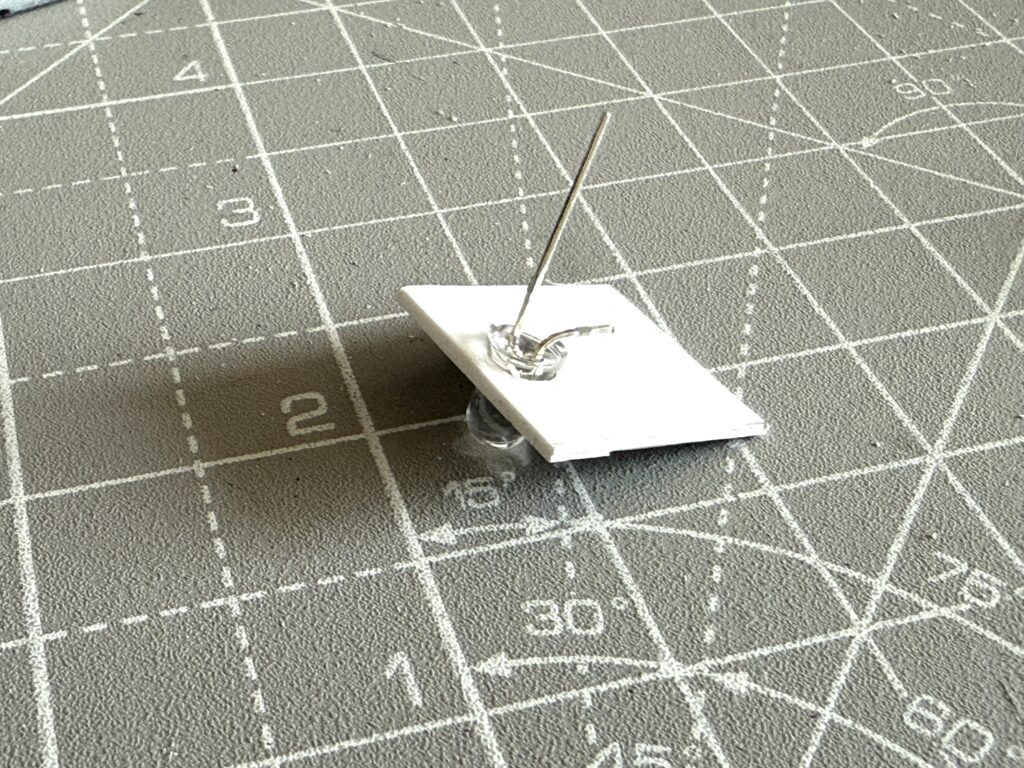
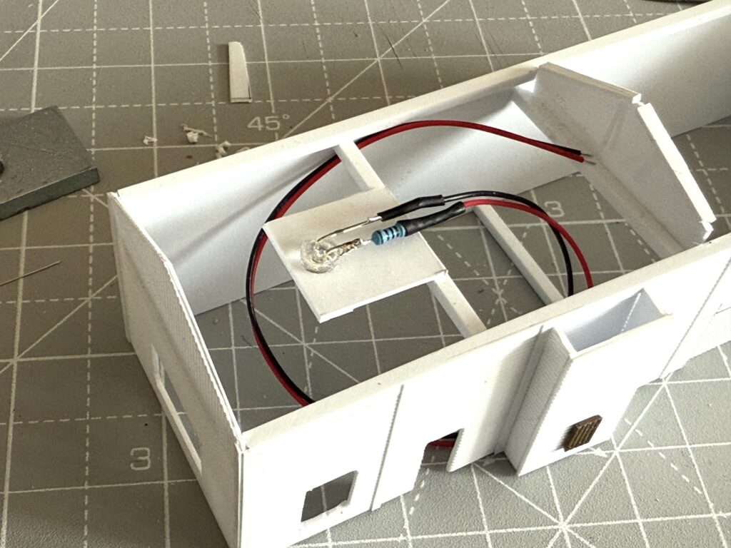
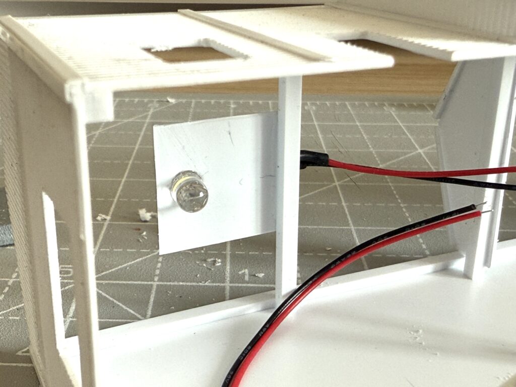
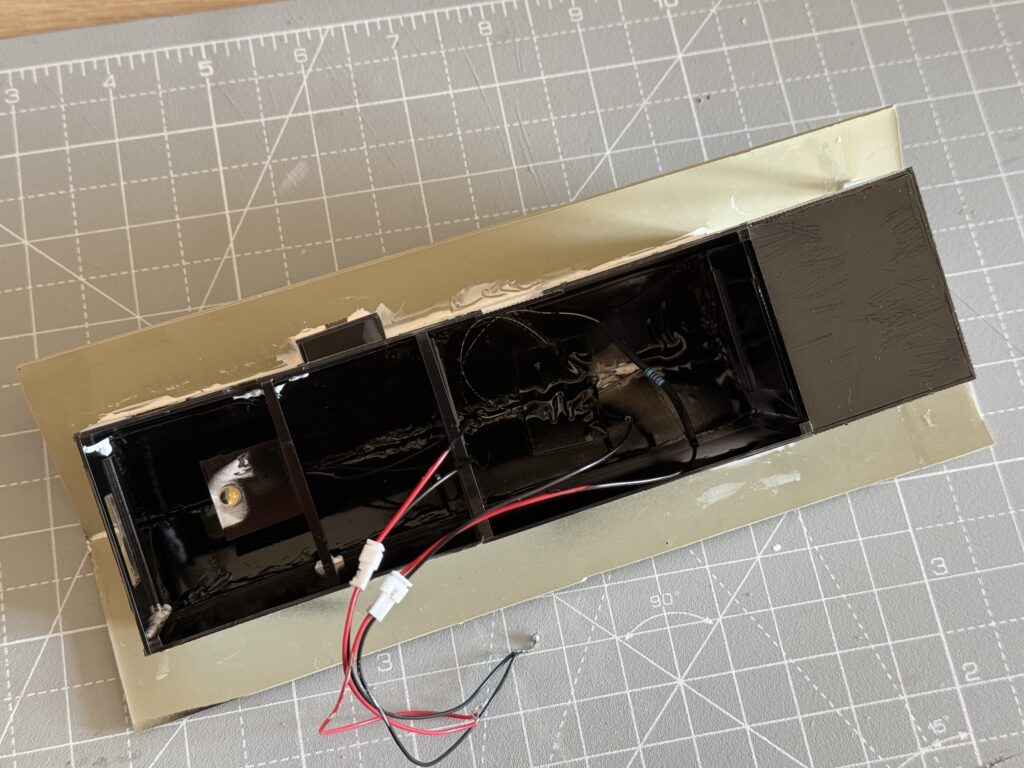
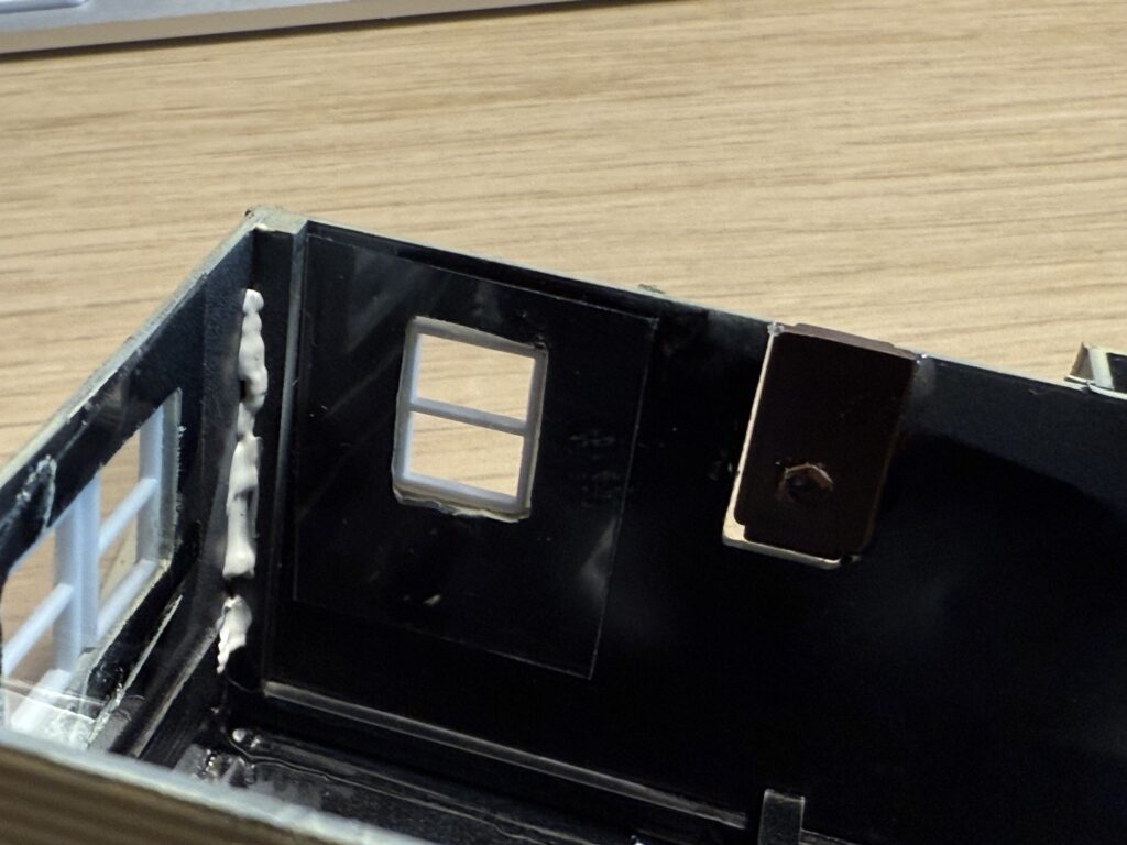
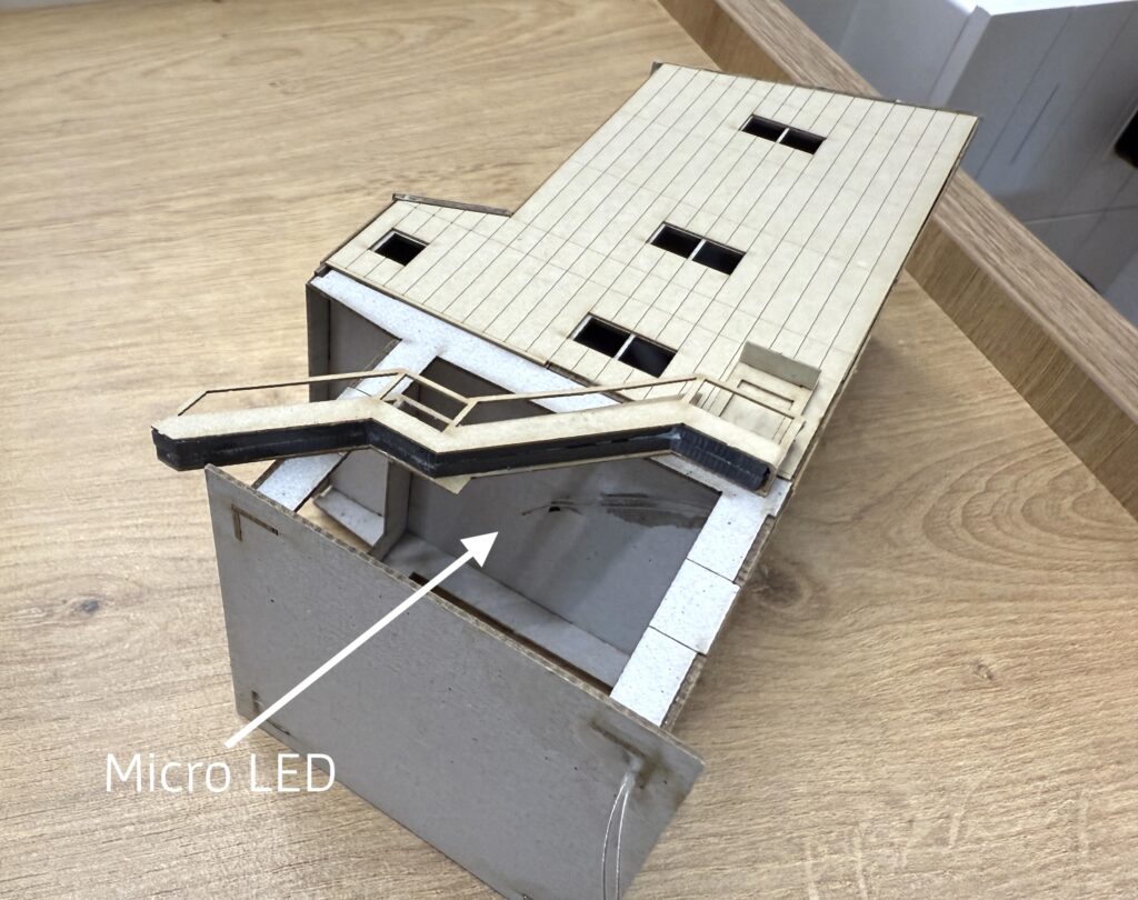
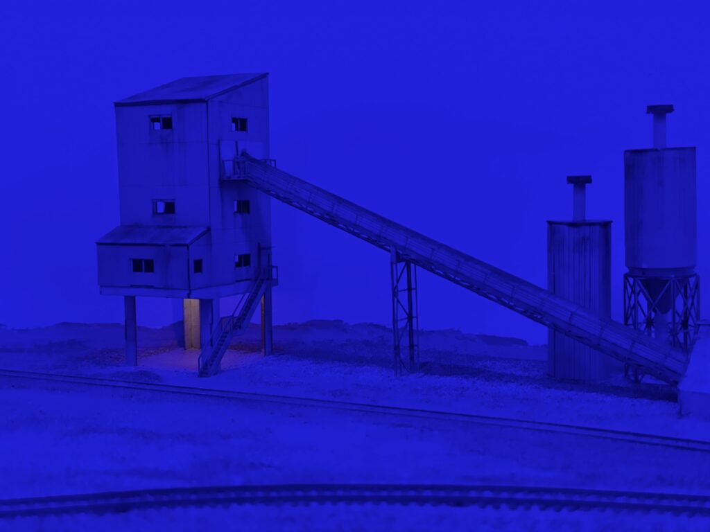
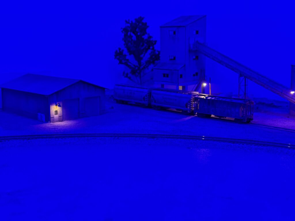
Before securing the structure to a sheet of styrene, which was later glued to the plywood base, I installed a micro LED to illuminate the scene at night. I secured the LED with CA glue and poked a hole in the structure base to run the wires through.
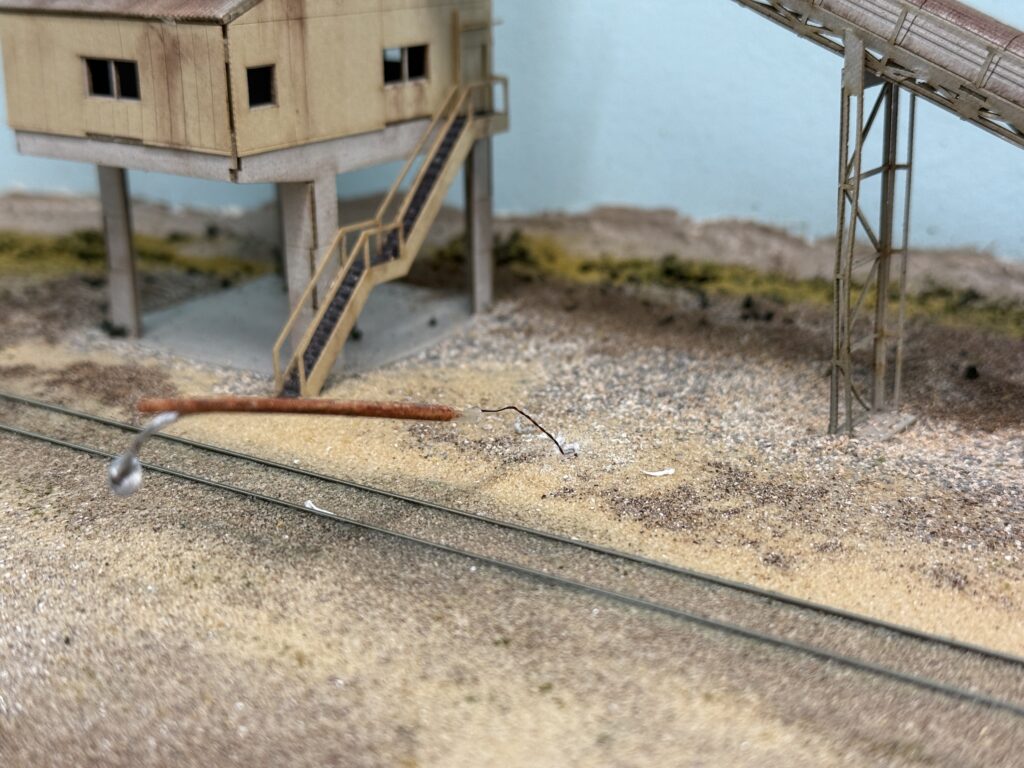
Adding Details
The cement plant is finally in place and it feels like the scene has gained real character. Next I will focus on adding life around it, because the area still looks a bit empty.
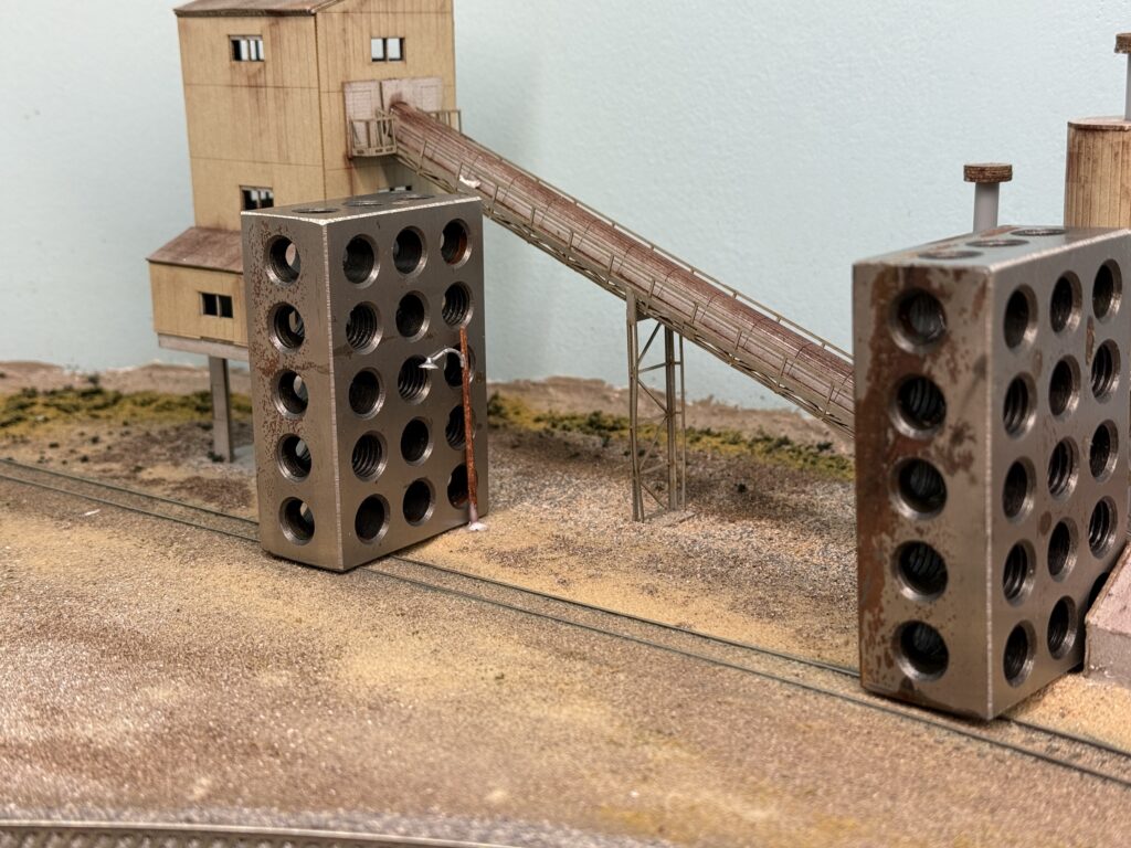
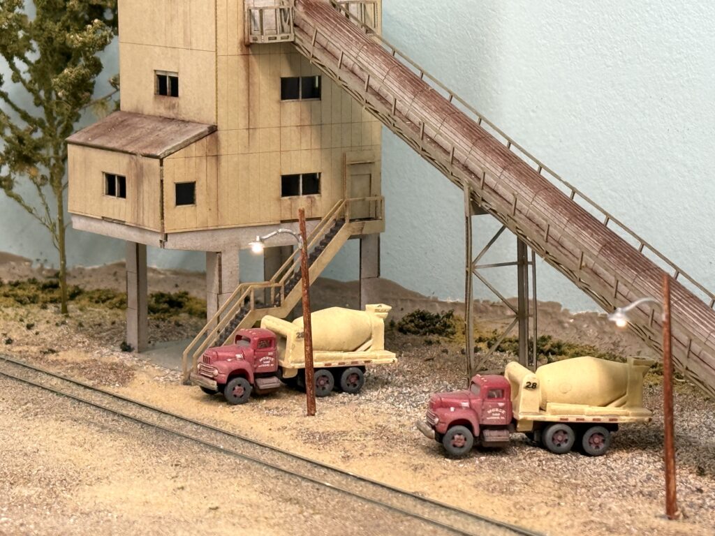
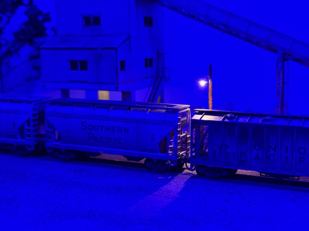
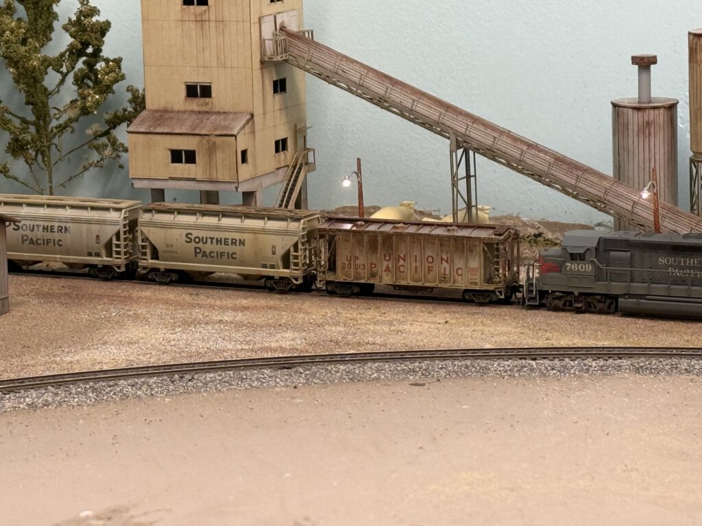
I added a couple of Woodland Scenics wooden streetlights. I drilled two holes, passed the wires through them, and glued the streetlights in place with matte medium. While the glue dried, I used some metal machine blocks to keep the poles in their final position.

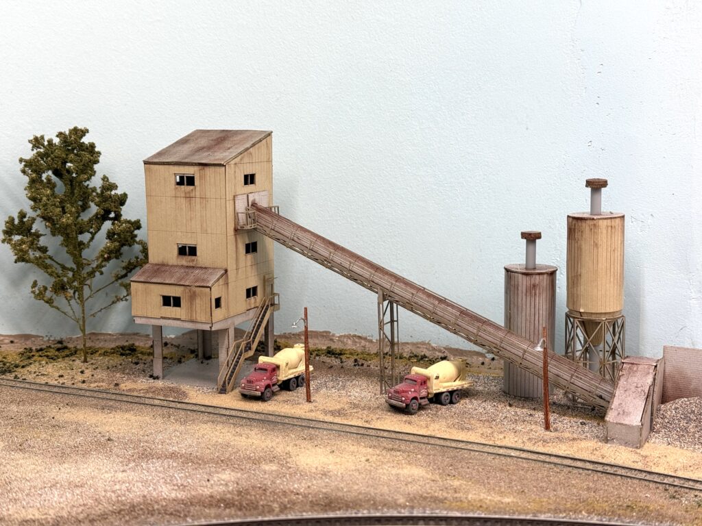
Afterwards I positioned a couple of concrete mixer trucks near the loading spots and added a tree.
Once more vegetation is set, I will install a metal fence to frame the whole structure. So the scene will grow step by step and the finished area should blend nicely with the rest of the layout.