Category: Benchwork

Installing a Bridge

Installing a Bridge over the Los Angeles River

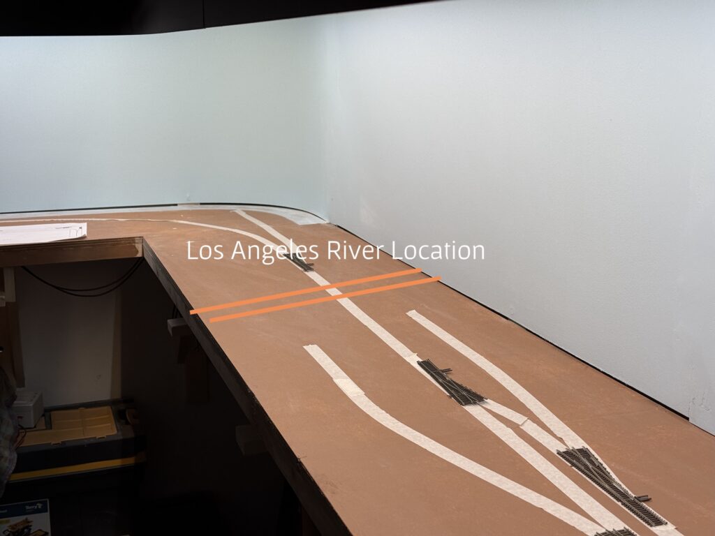
Installing a bridge over the Los Angeles River was high on my list, since river bridges have always fascinated me in model railroad layouts. In addition, bridges are a great way to add vertical variation to an otherwise flat urban setting, especially on a layout like the Burbank Branch in N scale .
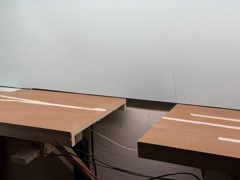
Cutting Benchwork

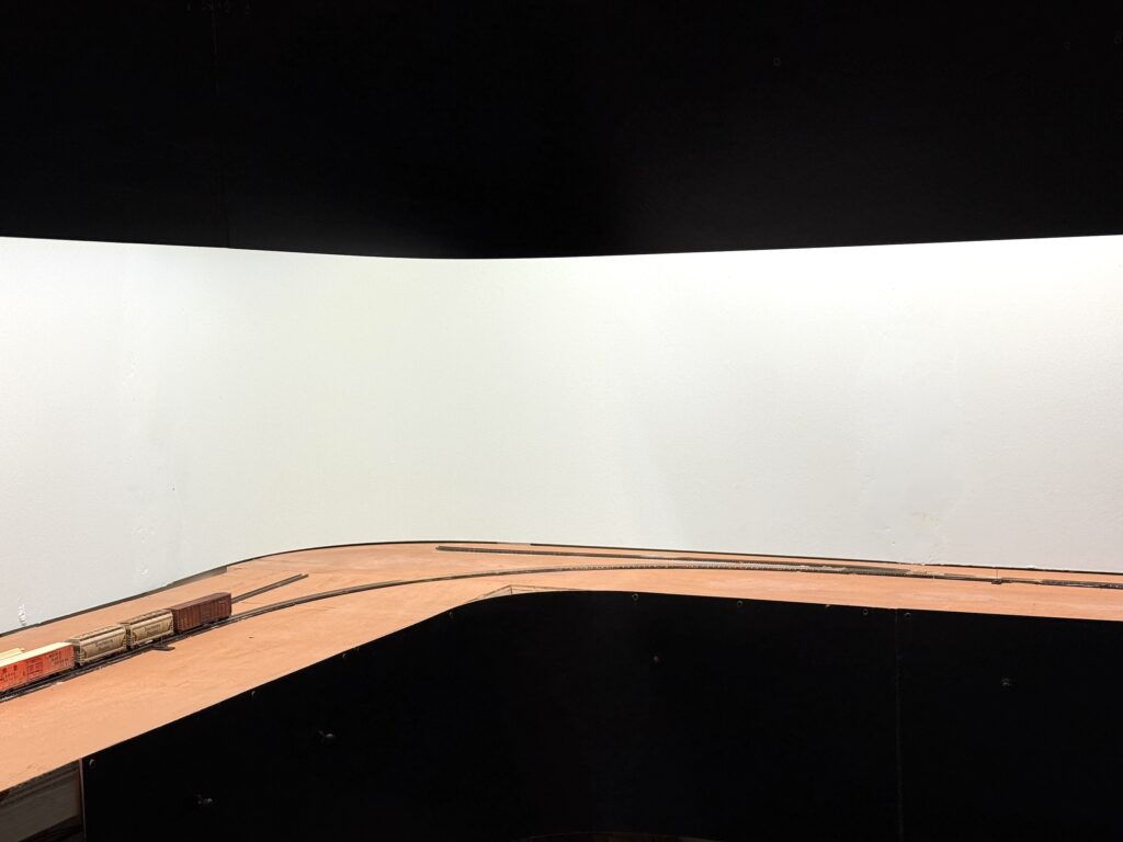
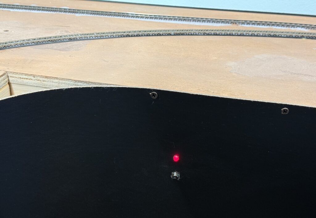
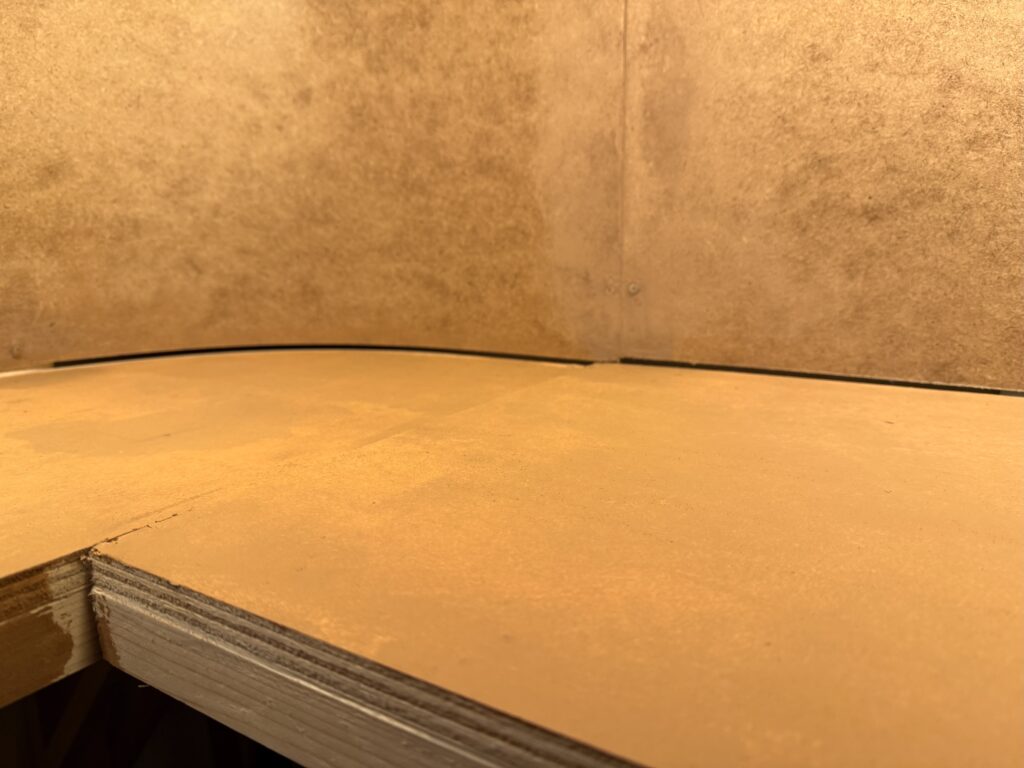
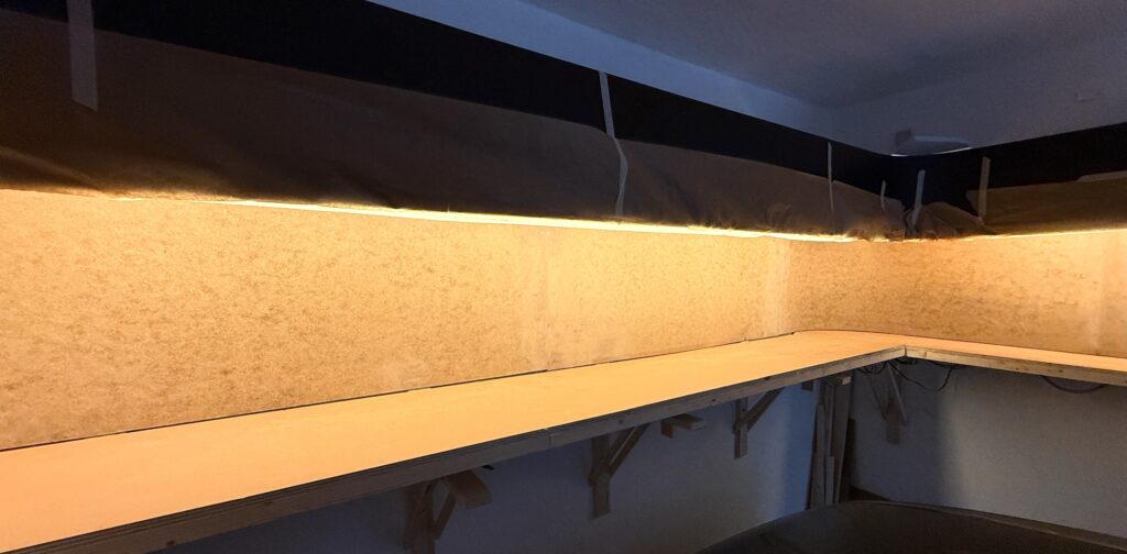
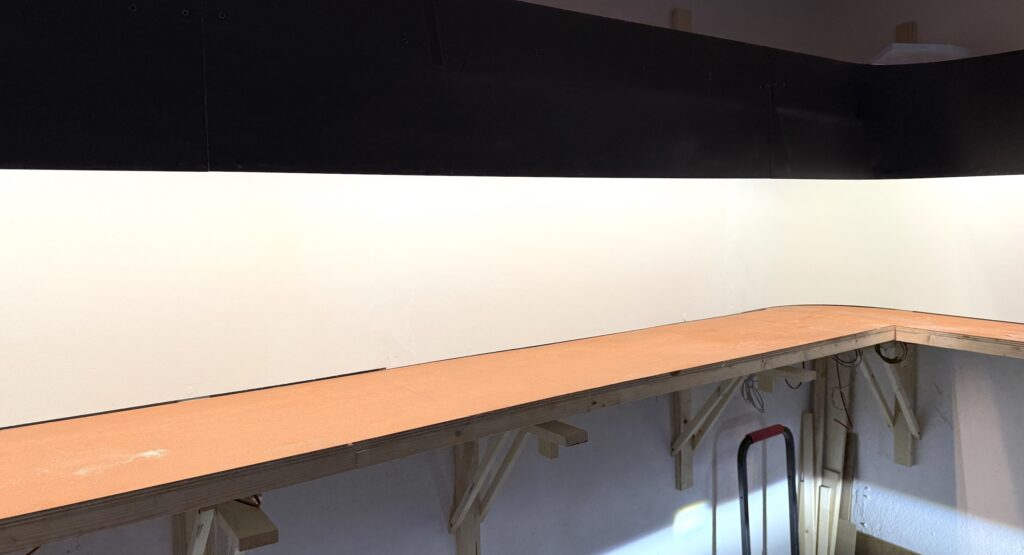
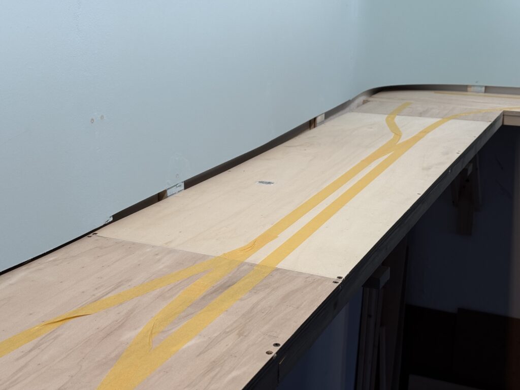
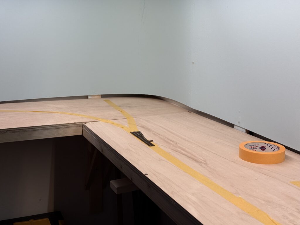
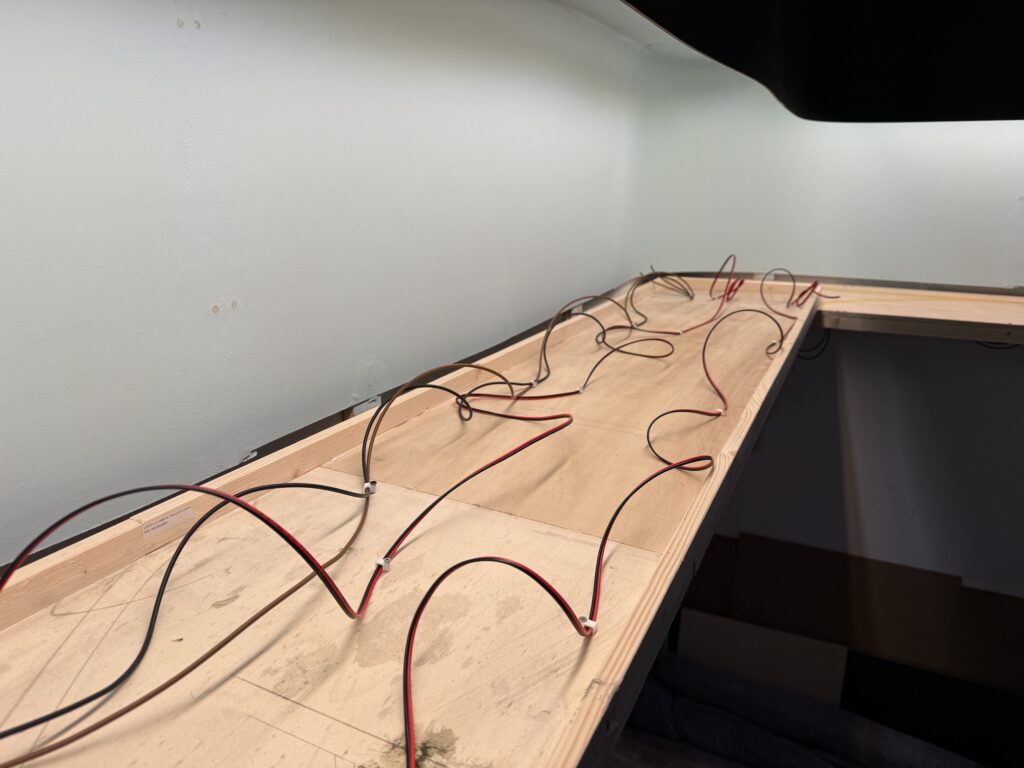
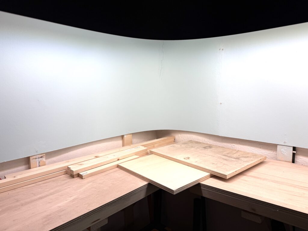
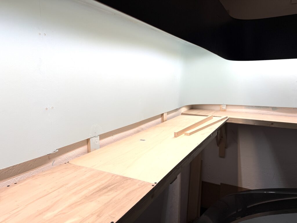
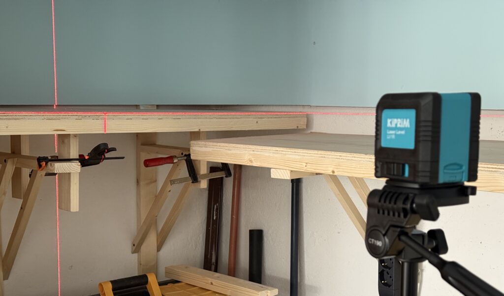
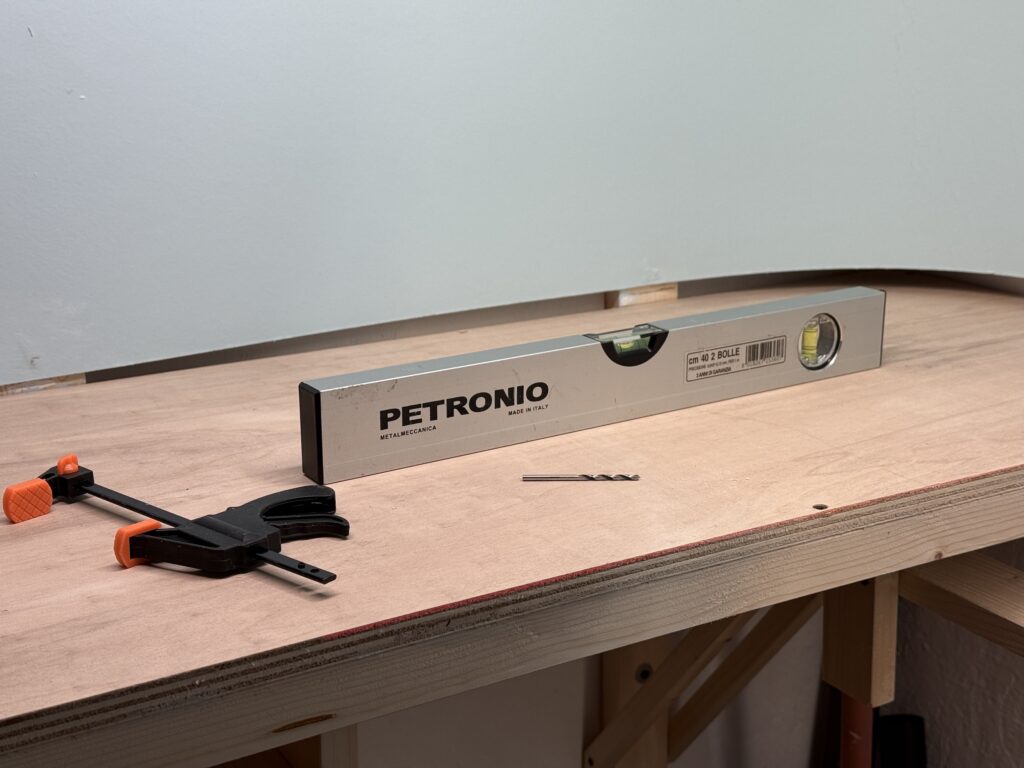
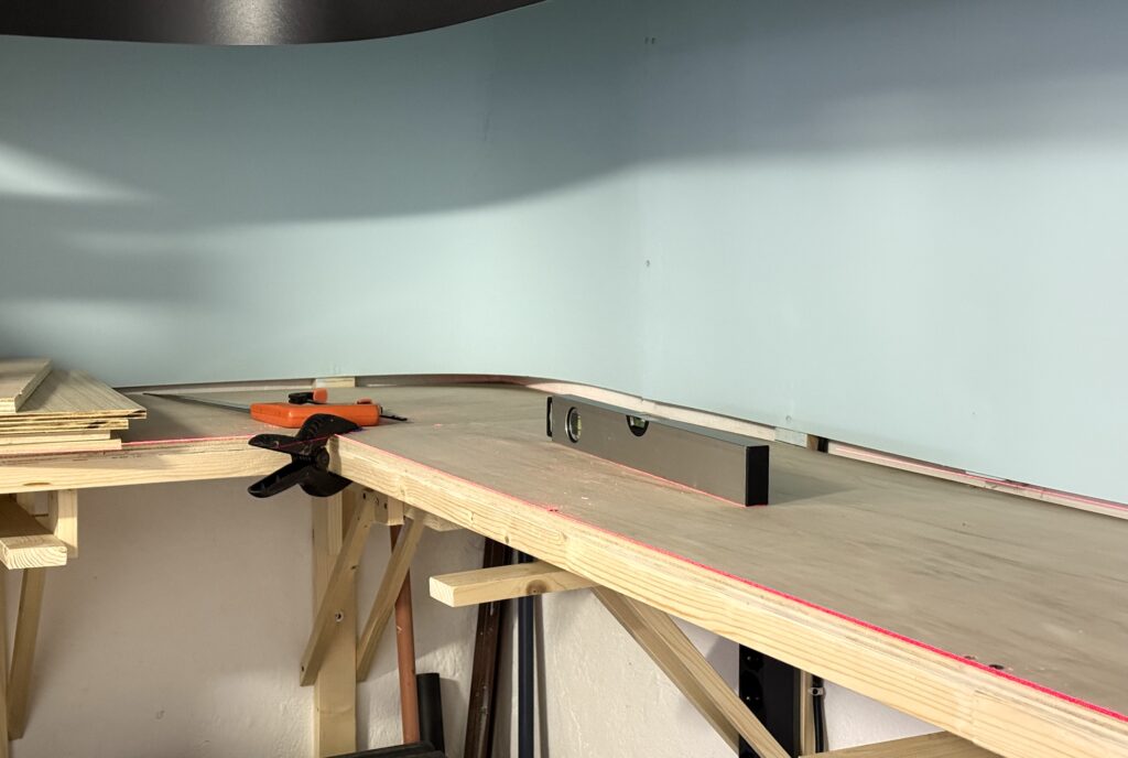
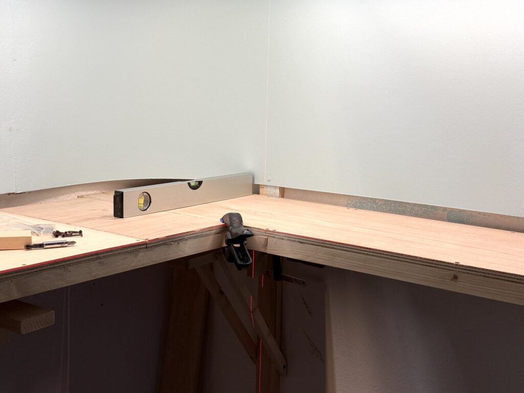
I started by measuring and cutting the plywood subroadbed support of my N scale layout.

Installing a bridge over the Los Angeles River
Cutting the benchwork

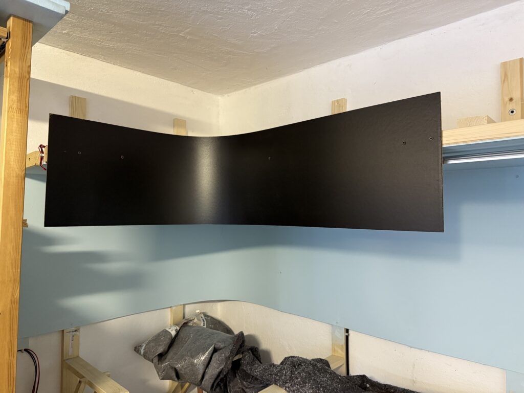
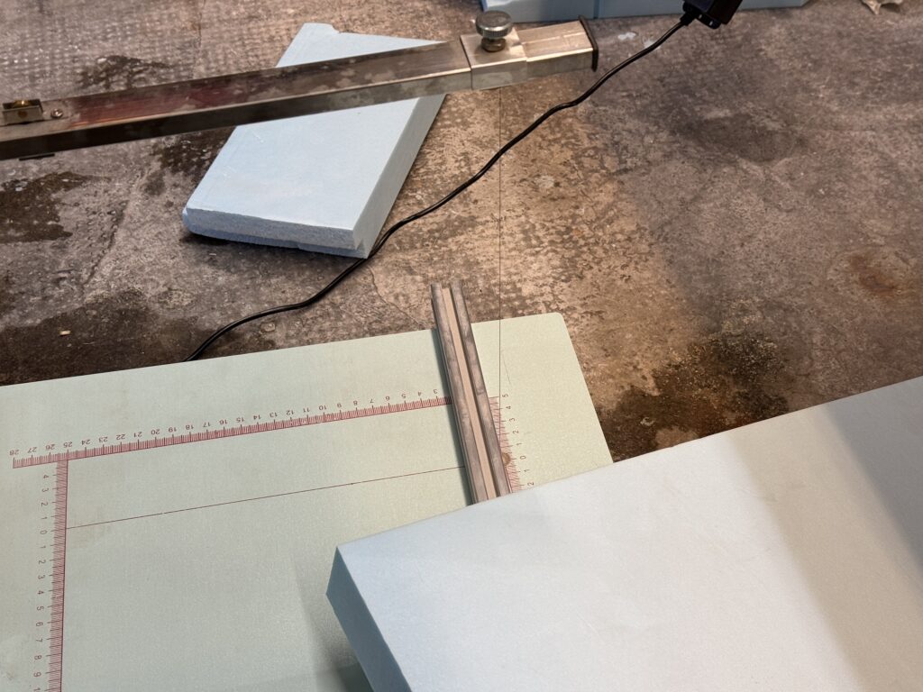
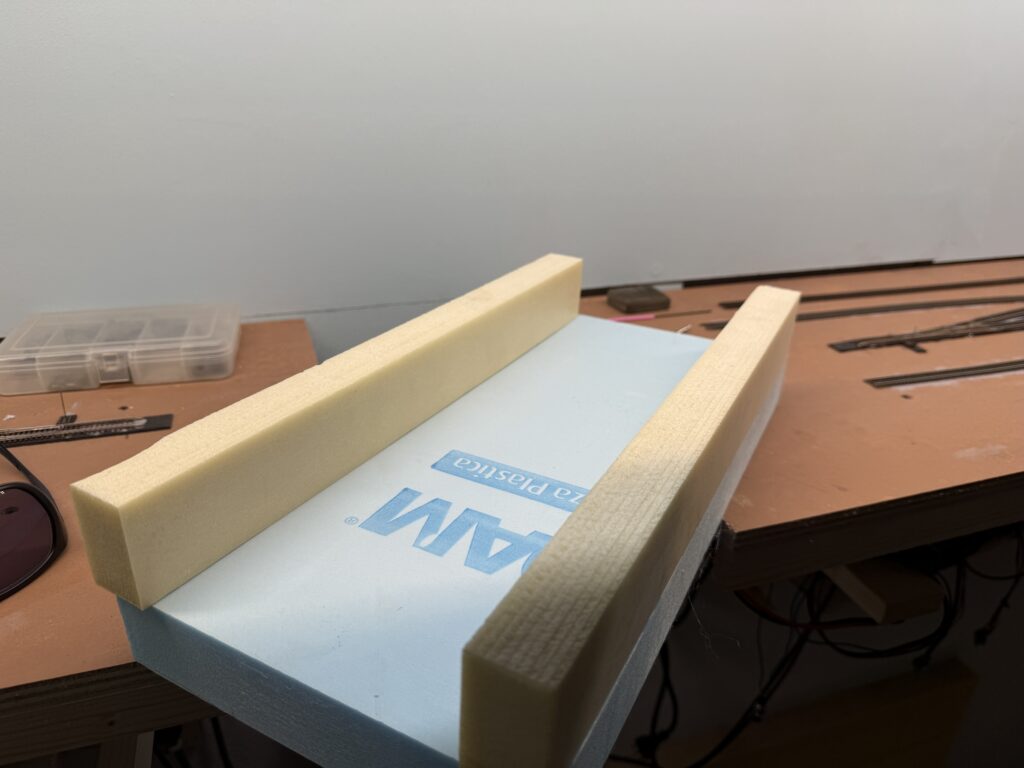
Then, I used styrofoam to shape the riverbed and the riverbanks, cutting it with a hot wire cutter.

Cutting foam with a hot wire cutter.

I glued the riverbanks to the riverbed with acrylic glue.

Installing a bridge: riverbed and riverbank made out of foam board.

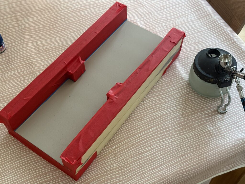
Next, I applied a few coats of ultra-flat gray spray paint to seal the foam and create a solid base for the final color, and masked the banks.

Installing a bridge: Painting the foam riverbed and river banks gray

I started painting the riverbed with a coat of Tamiya XF-8, then I progressively added light layers of Vallejo Camouflage Medium Brown (71.038), and Vallejo Light Green Chromate (71.006) to get some variation close to the riverbanks.

Painting the riverbed

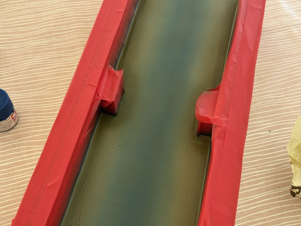
I painted the concrete riverbanks with a flat gray finish using an inexpensive spray can.

Expoxy Resin Water

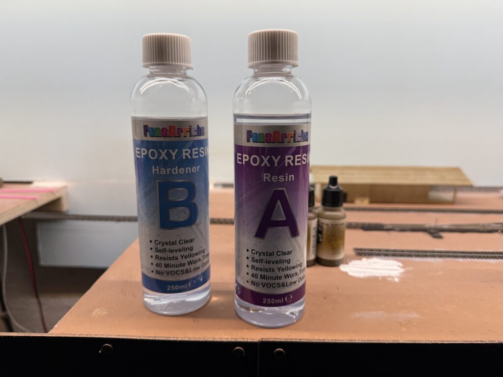
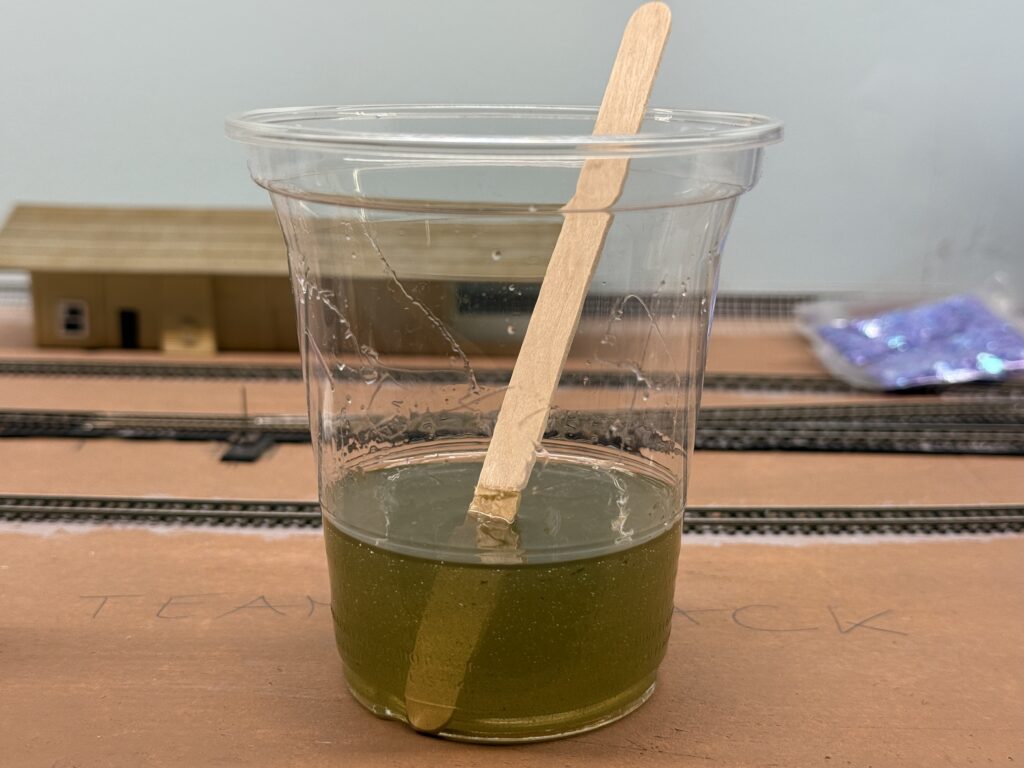
The riverbed and riverbanks are now painted. Therefore, they are ready for a layer of 2-part epoxy resin to achieve a realistic water effect.

Installing a bridge: 2-part epoxy resin.
2-part epoxy resin cups

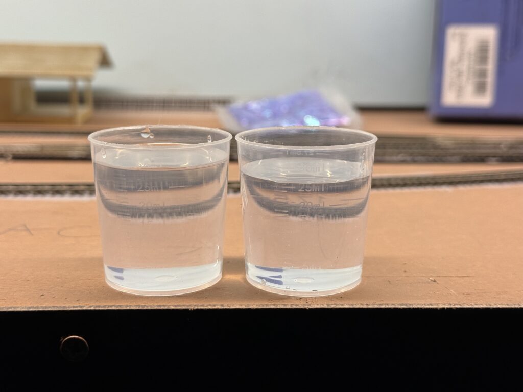
Always wear protective gloves when handling resin. After all, that material is incredibly sticky!

Mixing the 2-part epoxy resin.

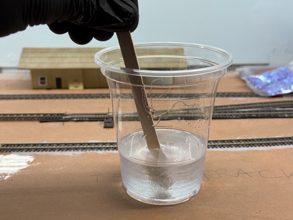
Additionally, I incorporated a few drops of Vallejo Dark Olive Drab (71.316). This gives the water a subtly greener, more natural appearance.

Adding drops of Vallejo Dark Olive Drab to the resin mix.

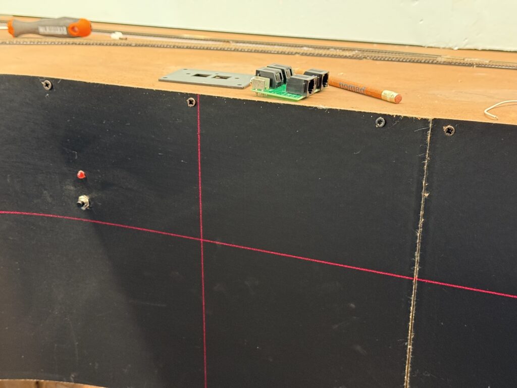
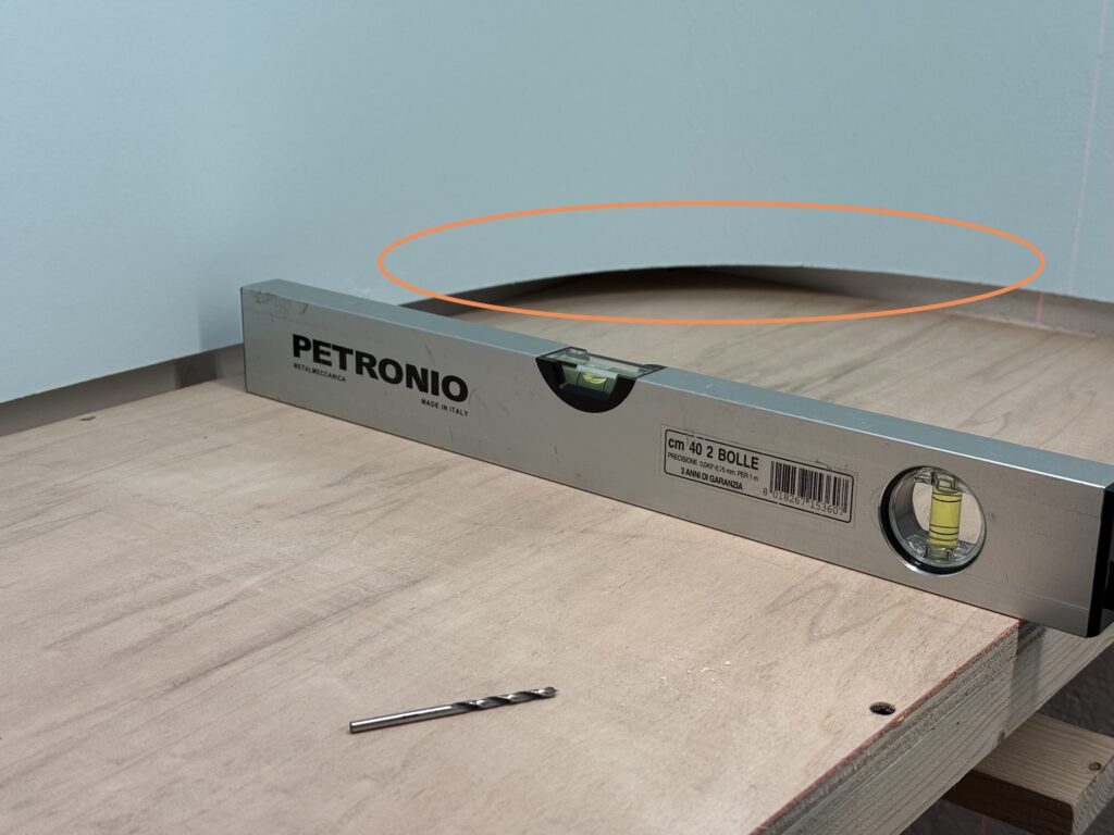
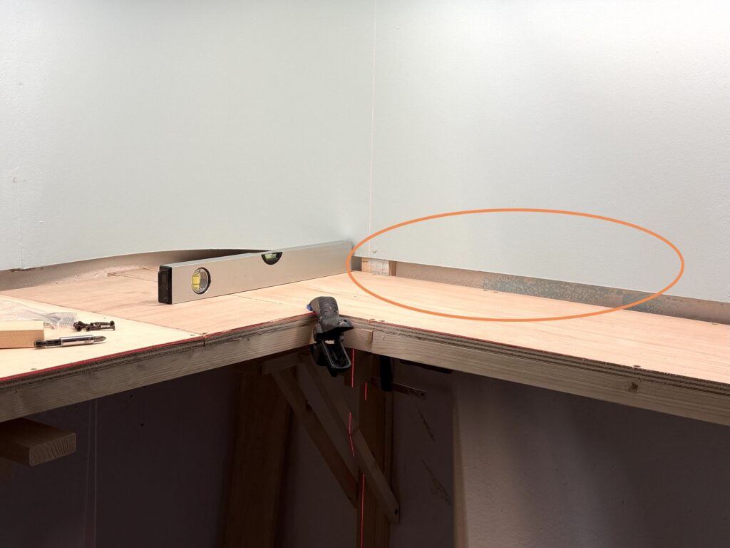
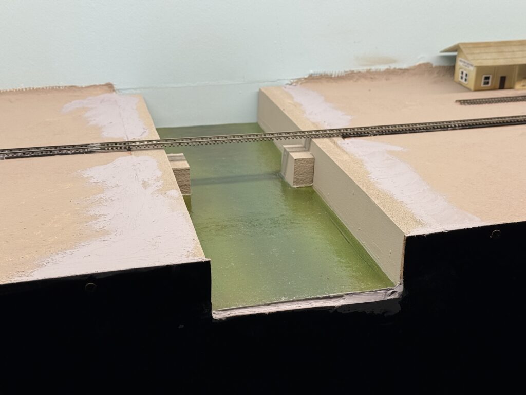
Once the resin had cured, I painted some subtle wave effect using Liquitex Gloss Medium. Then, I installed the riverbed in its final position on the layout. To ensure a perfect fit, I first test-fitted the riverbed and then marked the cutaway along the fascia with a pencil.

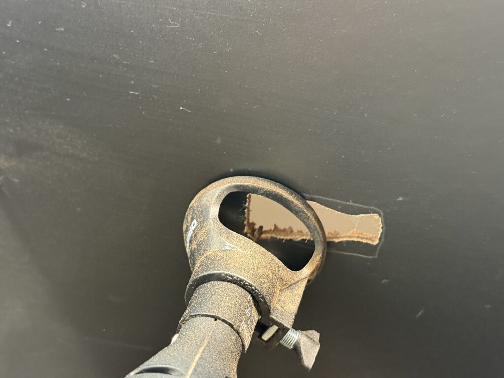
Subsequently, I cut the fascia accordingly with a saw. I then used a rasp and a file to fine-tune it.

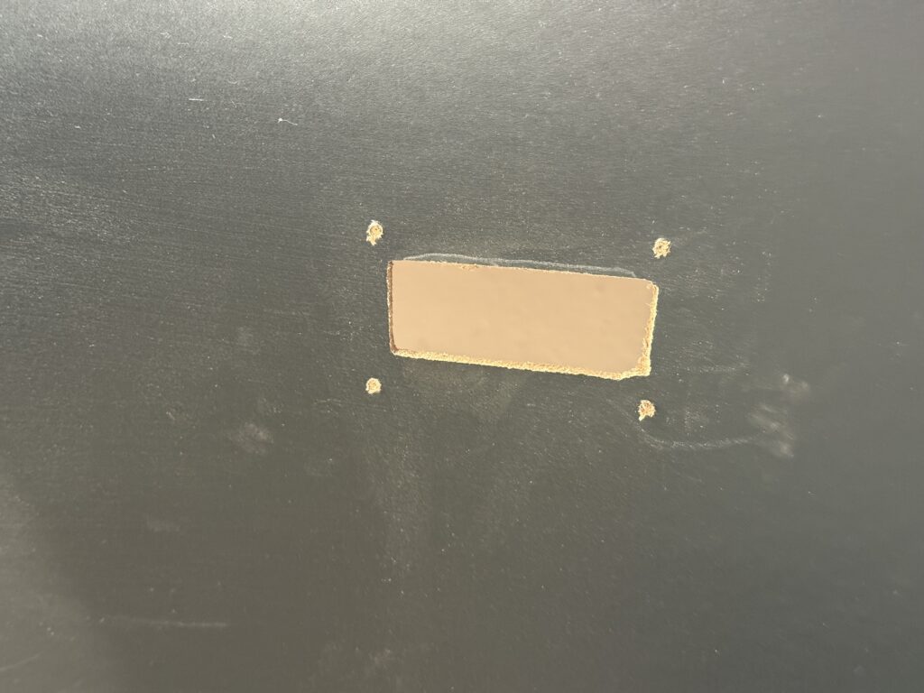
Finally, I glued the riverbed to the benchwork. Following this, I applied a layer of putty to smooth out the joints, creating a seamless transition.

LA River

Installing a Bridge: Final Steps

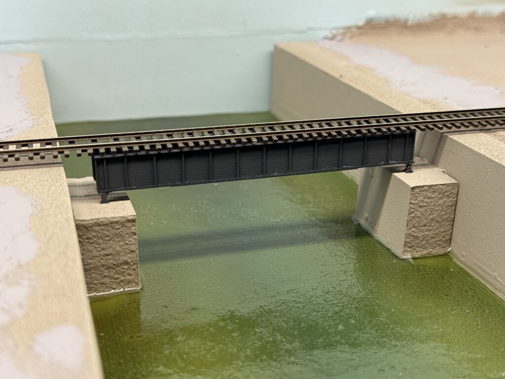
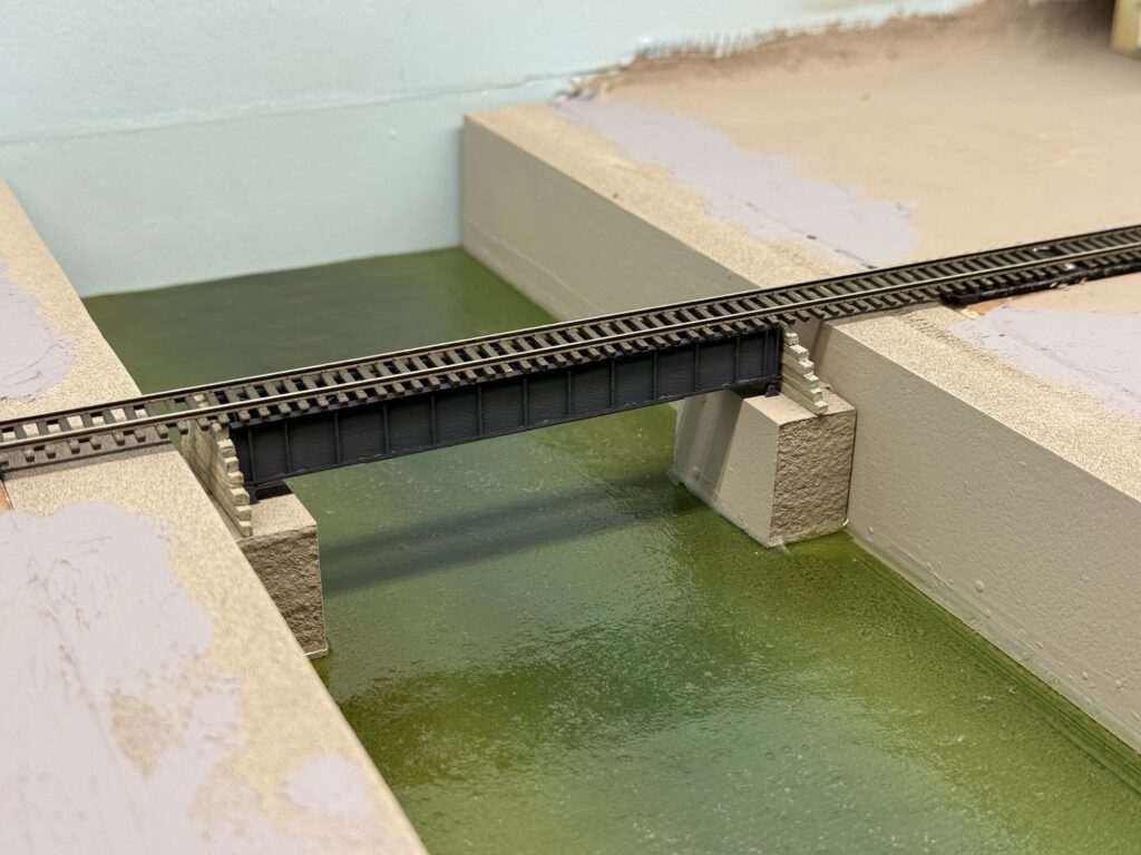
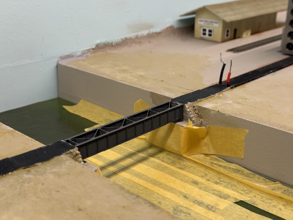
Then, I assembled an RSLaser 60-foot girder bridge kit and test fitted it in its final location.

Installing a bridge: test fitting the RSlaser kit.

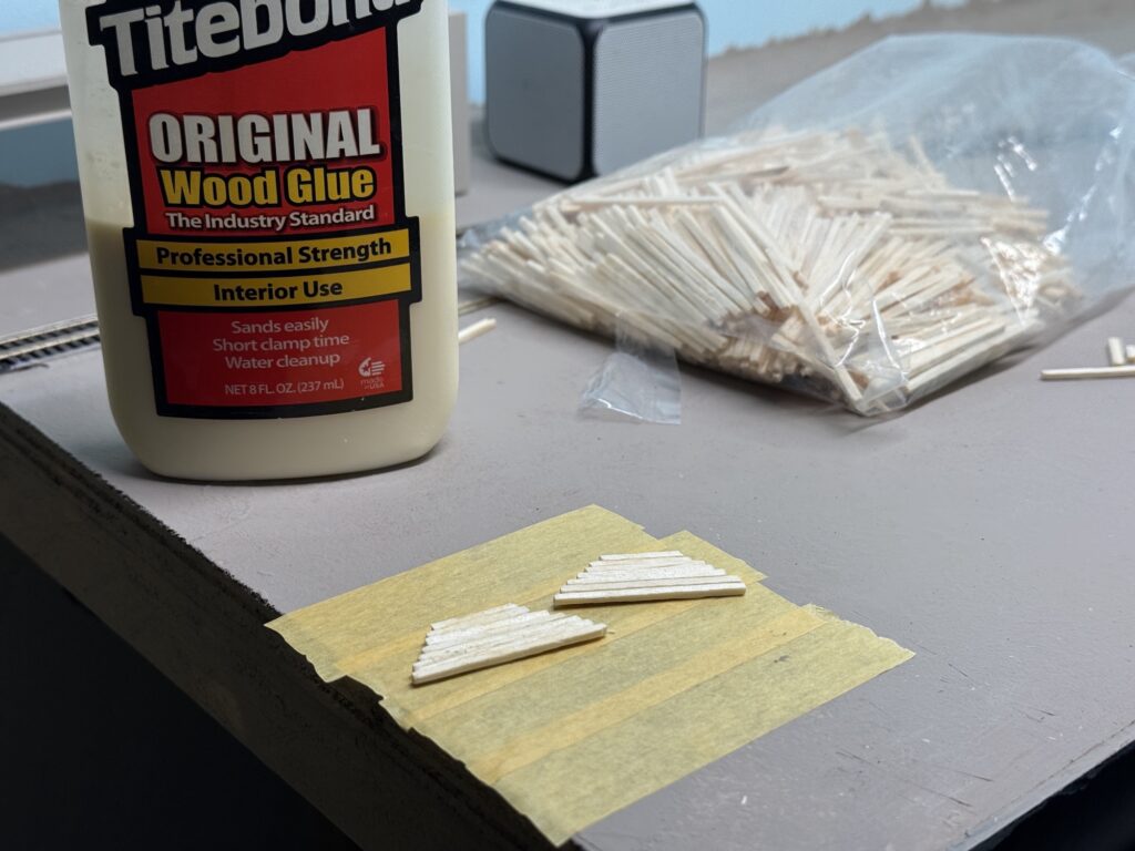
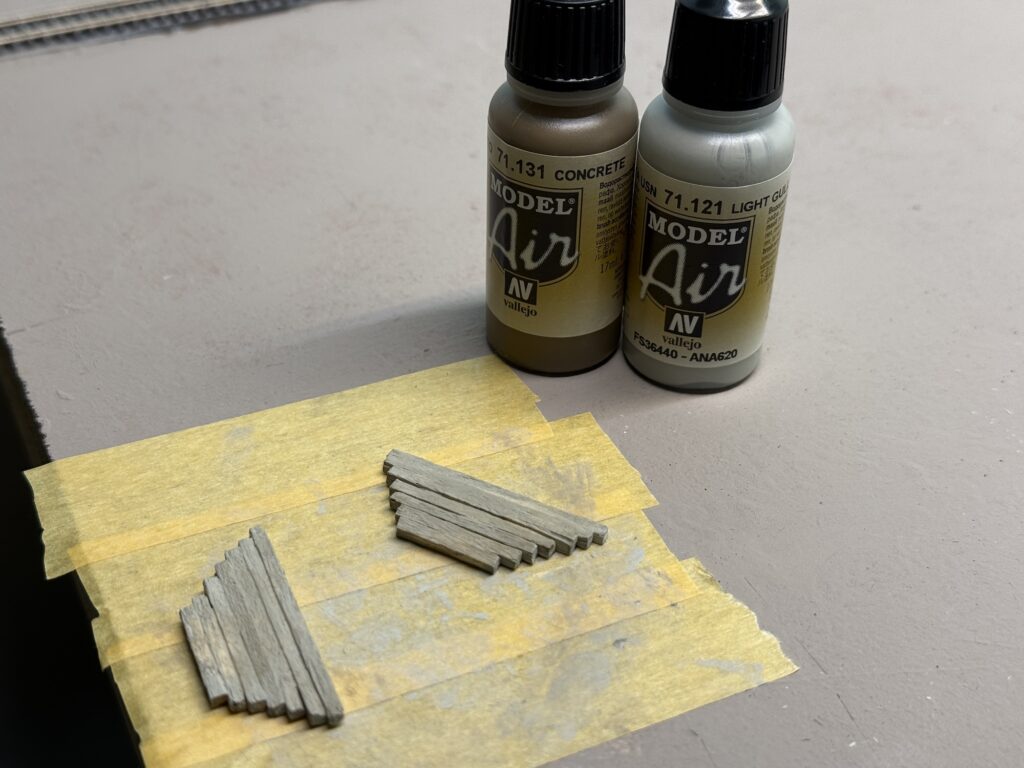
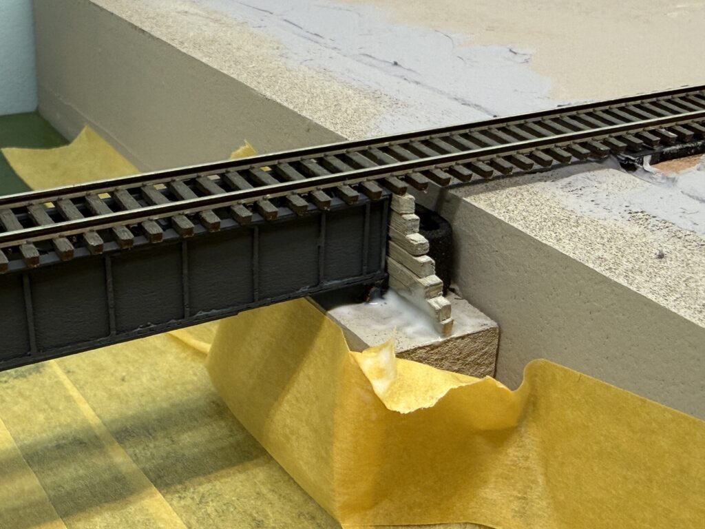
Afterwards, I scratchbuilt the retaining walls from tiny pieces of wood and painted them a warm gray tone using Vallejo Concrete and Vallejo Gull Gray. In the photo below, I’m test fitting them in place.

Retaining walls
Painting the retaining walls
Installing a bridge

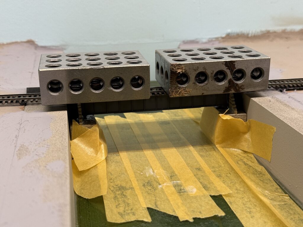
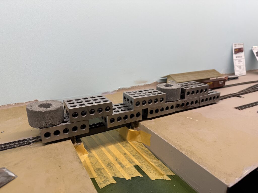
I glued the bridge to the abutments using Liquitex Matte Medium. Then, I secured the wooden retaining walls with more matte medium.

Glueing the bridge down with Liquitex Matte Medium
Retaining wooden walls glued

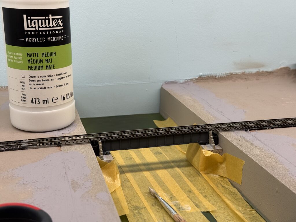
To keep everything aligned, I inserted a small piece of EVA foam to press the wall against the bridge. Afterwards, I placed a couple of metal weights on top of the bridge and let the glue dry.

Installing a bridge: keeping the bridge in place with metal weights

I added some papier-mâché terrain behind the retaining walls and painted everything a tan color.

Papier-mâché terrain behind the retaining wall

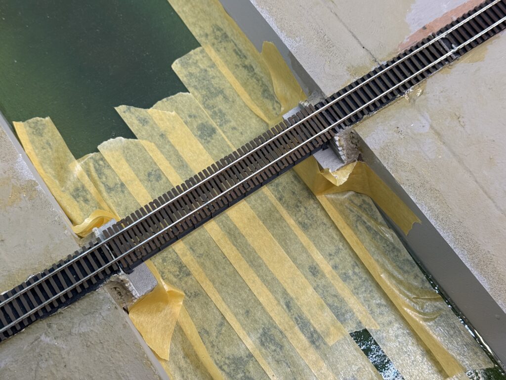
I prepared the bridge track with the correct tie spacing and soldered the feeders. Then, I carefully measured the section to install it in place of the temporary flex track I had used before the bridge was ready.

Installing a bridge: trackwork

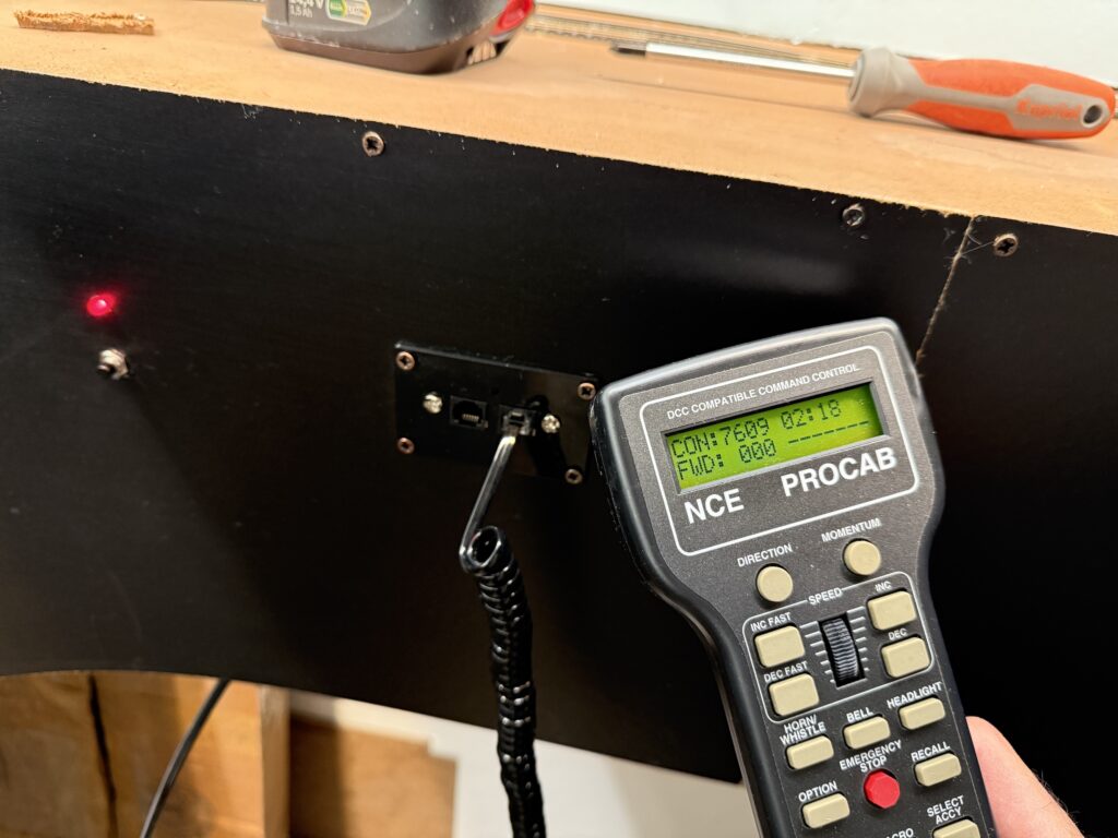
Once the track was in place, I connected all the feeders to the main bus, cleaned the rails, and tested the track.

Installing a bridge

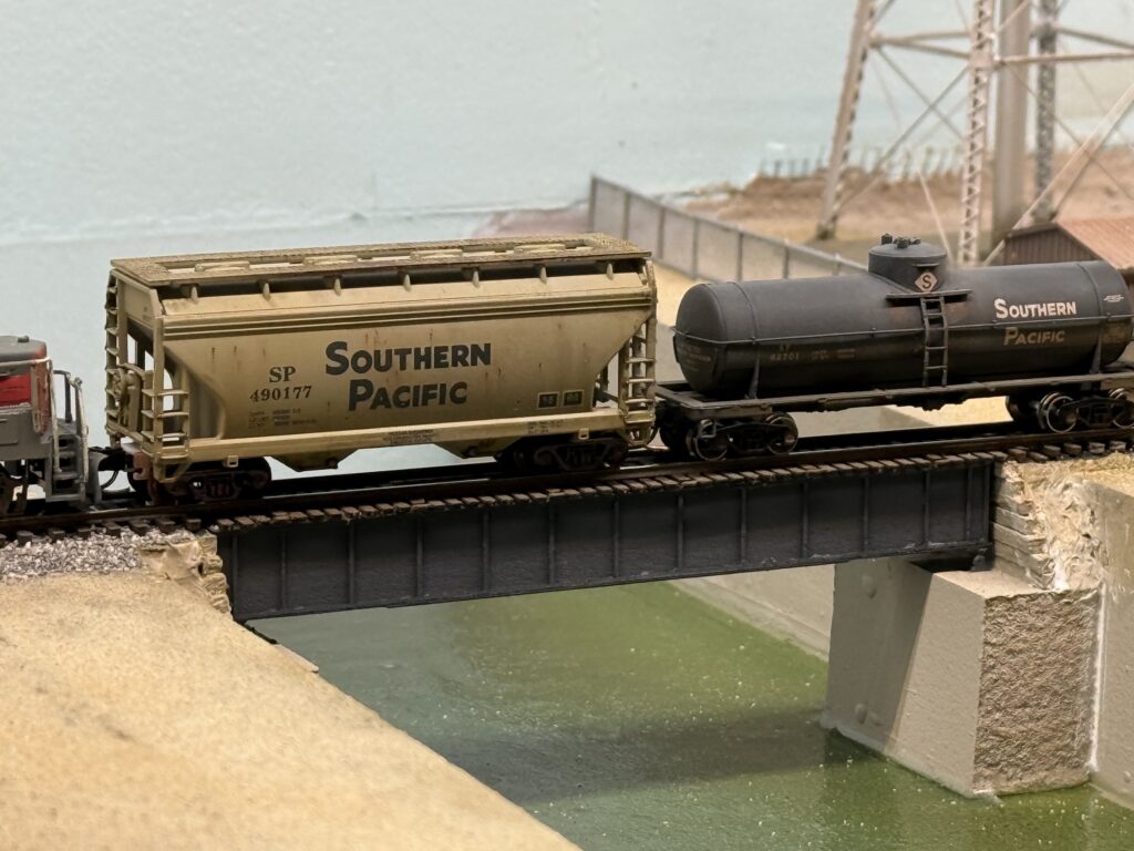
Here is the final result. It is still missing some terrain and vegetation around the edges, but overall the scene already feels much more complete.

Installing a Bridge

Adding a Fascia to the Layout

Adding a fascia to the layout for a neat look.

Adding a fascia gives the layout a clean, finished appearance. It also frames the scene and hides wiring underneath. The fascia also gives me a place to mount toggles and labels without cluttering the scene. I kept the design simple, just enough to tidy up without overcomplicating things.

Adding Fascia to the Layout

Toggle switches for turnouts are mounted near the turnout they control, making access easier and the track plan more intuitive. I designed a recessed mount for the toggle switch, which I plan to 3D print and install behind the fascia.

The recessed controls help keep the fascia flat and avoid accidental bump or damage during operating sessions.

Turnouts toggle switches
3D print drawing for a recessed toggle switch mounting plate.

I use Autodesk Fusion for 3D drawings. The personal edition is free for non-commercial use.

Power District Reset Button

I also installed red LEDs – one for each DCC power district – along with a push-button to reset the power breakers after a short.

Adding a Fascia to the Layout: power breaker LED and reset push-button.

I’ll fill the gaps in the curved section of the fascia with precisely cut extruded foam board.

NCE UTP Panels

Next, I measured and cut an opening for the NCE UTP panels, where the throttles will connect. Then, I used a Dremel with the appropriate bit to make the cut cleanly.

Laser level measurement for the NCE UTP Panels
I used a Dremel to cut the opening.

I refined the opening with a rasp. Then, I drilled four pilot holes for the NCE mounting plate.

NCE UTP Panel opening cut and refined.

The image below shows the NCE UTP Panel installed from the inside of the fascia.

NCE UTP Panel installed
Adding a Fascia to the Layout: Panel installed and NCE ProCab throttle connected

In the end, the fascia helps the layout feel finished, even while things are still in progress. It’s a small touch, but it goes a long way toward visual consistency and reliability.

The fascia adds both function and polish to the layout. Therefore, it hides clutter and supports controls. In addition, it frames the scene beautifully. I installed toggles and panels cleanly and efficiently. As a result, the layout looks more finished and cohesive, and overall operations feel easier and more enjoyable.

Backdrop Reboot

Backdrop reboot. Long story short: don’t be afraid of starting over.

It’s time for a backdrop reboot! I installed the valance and backdrop based on wall measurements, then installed the plywood subroadbed using a laser level. That’s when I realized the valance wasn’t level – and the culprit was the walls, not being square.

Free tip: Always use a laser level. They’re inexpensive and extremely useful – I wish I had bought one before installing the benchwork supports.

Huge gap.

The backdrop is mostly fine, with only a small gap on the west end of the layout. However, the gap increases toward the east, as shown in the photo above. While the plywood base is level, the backdrop has a slight but steady incline.

At first, I thought I could fix it since the scenery isn’t done yet. But I quickly realized that the area I’m modeling is flat, with little vegetation – no hills or dense forests to hide the gap.

Backdrop reboot: huge gap between backdrop and plywood base.

I tried thinking of a solution, but the more I considered it, the more I realized the backdrop needs to be scrapped and redone from scratch. So I did.

Starting over

Backdrop reboot! I carefully unscrewed and removed the old backdrop, taking care not to damage the LED strip lights or valance. Then, I installed new Faesite (Masonite) panels, aligning the backdrop with the subroadbed plywood base.

Better looking gap between faesite (masonite) panels and plywood base

After installing the backdrop, I filled the gap with putty and smoothed it out. Now it’s ready for a coat of blue paint.

Backdrop ready to be painted blue

Using acrylic colors, I painted the plywood base tan. That serves as a basic color for the scenery.

Starting over can be frustrating, but fixing mistakes early prevents bigger issues later.

Backdrop reboot: finished!

Fixing backdrop issues early builds confidence and prevents bigger layout problems down the line. A properly aligned backdrop sets the stage for convincing scenery.

Now I’m ready for some trackwork.

Trackplan and Wiring

Transfer the trackplan on plywood and start wiring the DCC and DC buses

Trackplan

I used masking tape to transfer the trackplan onto the plywood base, then started wiring the DCC and accessory DC buses.

test-fitting the trackplan using masking tape
Trackplan and wiring: test-fitting using masking tape

What works on paper doesn’t necessarily translate well to the layout. I like to use masking tape to sketch a rough version of the trackplan directly on the plywood subroadbed, allowing me to test-fit curves, sidings and spurs.

Wiring

There are three main buses running under the layout:

  • DCC bus, using 2.5mm² wires (14 AWG)
  • 12VC DC bus for Tortoise switch machines, using 0.75mm² wires (18 AWG)
  • 12VC DC bus for lighting, including streetlights and structure lights, using 0.75mm² wires (18 AWG)

I flipped the plywood base and started fixing the bus wires in a temporary, untidy manner. I will clean up the wiring once all the track feeders and Tortoise switch machines are installed, so that I can determine the correct length for each wire.

Plywood base flipped and wire bus installed
Trackplan and wiring: temporary length bus wires installed.

To tap power without cutting or stripping main wires, I used suitcase connectors – quick, reliable, and ideal for temporary setups. They let me add feeders or accessories on the fly, which is perfect while I’m still fine-tuning the layout.

This approach saves time now and prevents headaches later when the layout is more complete.

Wiring the layout with DCC and accessory power requires both solid planning and a bit of foresight. I installed a robust DCC bus using heavy-gauge wire for consistent power delivery, with feeders soldered in regularly to avoid voltage drops.

Accessory wiring, like 12V DC lines for Tortoise machines and lighting, runs separately for clarity and ease of troubleshooting.

While the system is built to be dependable, I’ve allowed for future adjustments – leaving a bit of slack, labeling connections, and routing wires with accessibility in mind. Layouts evolve, and the wiring can too.

Plywood Subroadbed

Building a plywood subroadbed using 15mm-thick plywood

For a switching layout, using a plywood subroadbed is an easy and relatively quick way to establish a solid foundation for the trackwork.

Plywood subroadbed
Plywood subroadbed with longitudinal supports

I had the plywood cut to size for each of the three main sections of the layout (see track plan). Then, I reinforced the plywood base by gluing and screwing down 20mm x 35mm lumber.

I then prepared risers to hold the plywood base at the proper height (140cm – about 55″). However, I haven’t attached the base to the risers yet.

I used a laser level I bought on Amazon to install the risers at the correct height. First, I clamped the risers to the benchwork, then I double-checked that the plywood base was level with the laser line. Once everything was aligned, I drilled pilot holes in the risers and screwed them down to the benchwork.

Using a laser level
Laser level to help installing benchwork
Laser level purchased on Amazon

Using a laser level speeds up the entire construction process. I keep it on throughout the session for a constant visual reference. Then I double-checked with an old-school level 🙂 to ensure everything was at the correct height and perfectly level.

Checking with old-school level
Checking plywood subroadbed with an old-school level

I proceeded with installing the risers for the three main subroadbed sections. The plywood base is just resting on the risers for now. The reason for that is I want to be able to flip the base to wire the tracks and Tortoise switch machines more comfortably.

Installing the plywood subroadbed
Plywood base

A 15mm-thick plywood subroadbed provides a sturdy foundation, ensuring durability and stability for trackwork and scenery on my N scale layout.

Using pre-cut plywood sheets speeds up construction, reducing material waste and simplifying layout assembly. Reinforcing the plywood with lumber prevents warping and keeps the track level over time. Wiring and switch machine installation are more accessible by flipping the plywood base during construction.

This method is ideal for switching layouts, offering a reliable and efficient track-laying surface.

Installing the valance

Using Faesite (Masonite) sheet, installing the valance is quick and easy.

I purchased some black Faesite (Masonite) sheets, had them cut to length, and used them to install the valance. A valance helps direct and diffuse light onto the layout while preventing glare from LED strips or other light sources.

Below is a short video showing the final result with LED lighting on my N scale layout.

Valance Installation

Just like with the backdrop, I bent the board to create a smooth, rounded corner.

Installing the valance
Valance installed on the layout

Enhanced Visual Framing

The LED strips are hidden behind the valance. Installing the valance creates a more immersive and finished look by framing the scene and keeping the viewer’s focus on the trains and scenery. The valance helps conceal ceiling lights, room clutter, and other distractions outside the layout.

LED strips hidden behind the valance

Depending on the height and depth of the valance, the valance may make the layout feel more enclosed or get in the way of taller operators. Also, installing a valance requires additional materials, cutting, mounting, and possibly bending for curved corners.

That said, a well-designed valance adds a professional touch, making the layout appear more polished and realistic.

Lighting

I use three LED strips of different colors: 2700K, 4000K and blue light. Each strip is wired to a dimmable power supplies and dimmers , allowing independent control. Remote push-buttons control the lights. I used Italian brand Bticino Matix Go push-buttons.

Push-buttons to control the LED strips

I usually use a combination of 4000K and 2700K for daylight, while the blue light is on for night operations. In the photo below, the blue appears more saturated than it does in person.

Installing the valance: 4000K + 2700K
Blue light for nighttime operations

A well-planned valance and lighting setup transforms the look and feel of a model railroad. By combining different LED color temperatures, it’s possible to replicate natural lighting transitions, enhancing realism without drawing attention away from the trains.

Adjustable dimming and remote controls add convenience, allowing for seamless shifts between day and night scenes. Thoughtful lighting makes a huge difference in bringing the layout to life while keeping the focus on the trains and scenery.

LED Strips Installation

LED strips installation behind the valance

I started the LED strips installation by fixing the aluminum profiles on the valance ceiling, to light my N scale layout. The profiles are great for holding the LED strips in place and dissipating the heat they generate.

I initially planned to use only two LED strips – one 4000K and one 2700K – with dimmers to adjust the lighting color combination. Then, I decided to add a third blue LED strip for night operations. I’m not sure if I’ll use the blue LED strip, but I figured it would be easier to install it now rather than add it later.

LED Strips Installation: aluminum profiles

I cut the aluminum profiles to length and screwed them into the valance ceiling.

I cut the aluminum profiles to length

I then measured and cut the LED strips, soldering short wires to connect the corners. The LED strips are self-adhesive, so I proceeded securing them to the aluminum profiles.

Securing the LED strips with self-adhesive tape.

Illumination

After installing the LED strips I quickly realized they mainly illuminated the area directly beneath them. Part of the backdrop was clearly left in shadow. I needed to mount the LED strips at an angle to minimize the shadow effect.

LED strips illuminating the layout area.

Door wedges to the rescue! I purchased some wooden door wedges and I used them to mount the LED profile holders at an angle.

Wooden door wedges used to mount the LED strips at an angle
LED strip installation at an angle

The LEDs installed at an angle provide better illumination for the entire area. Below, you can see the three strips turned on: 2700K, 4000K, and Blue light.

All three LED strips are turned on: 2700K, 4000K and Blue light.

The next step is installing the valance using Faesite (Masonite) board. The valance helps frame the layout and masks the LED lights, preventing them from shining directly into the operators’ eyes.