Author: admin

Track Ballast

Adding track ballast to the Burbank Branch in N scale

Adding track ballast is one of my favorite parts of the process. It is the stage when a model railroad truly starts to take shape and look real, like when I painted the track.

Afterwards, I used Woodland Scenics fine ballast as I usually do. This time I mixed equal parts of Gray (B1375) and Light Gray (B1374). I spread the ballast with a spoon, then shaped it carefully with my index finger and a soft paintbrush.

Track ballast

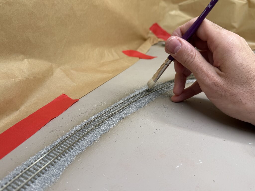
After that, I made sure no ballast remained on the ties or along the rail sides. I also payed special attention to the turnouts, usually avoiding the points area altogether.

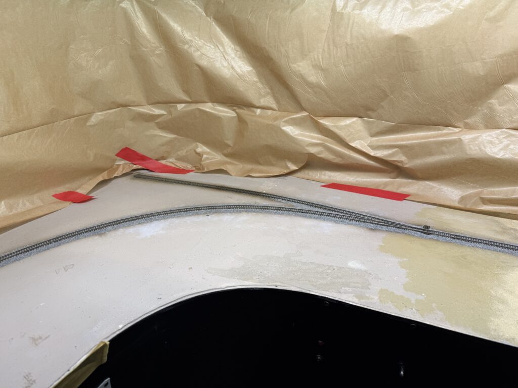
With some careful painting, it is easy to disguise the missing ballast.

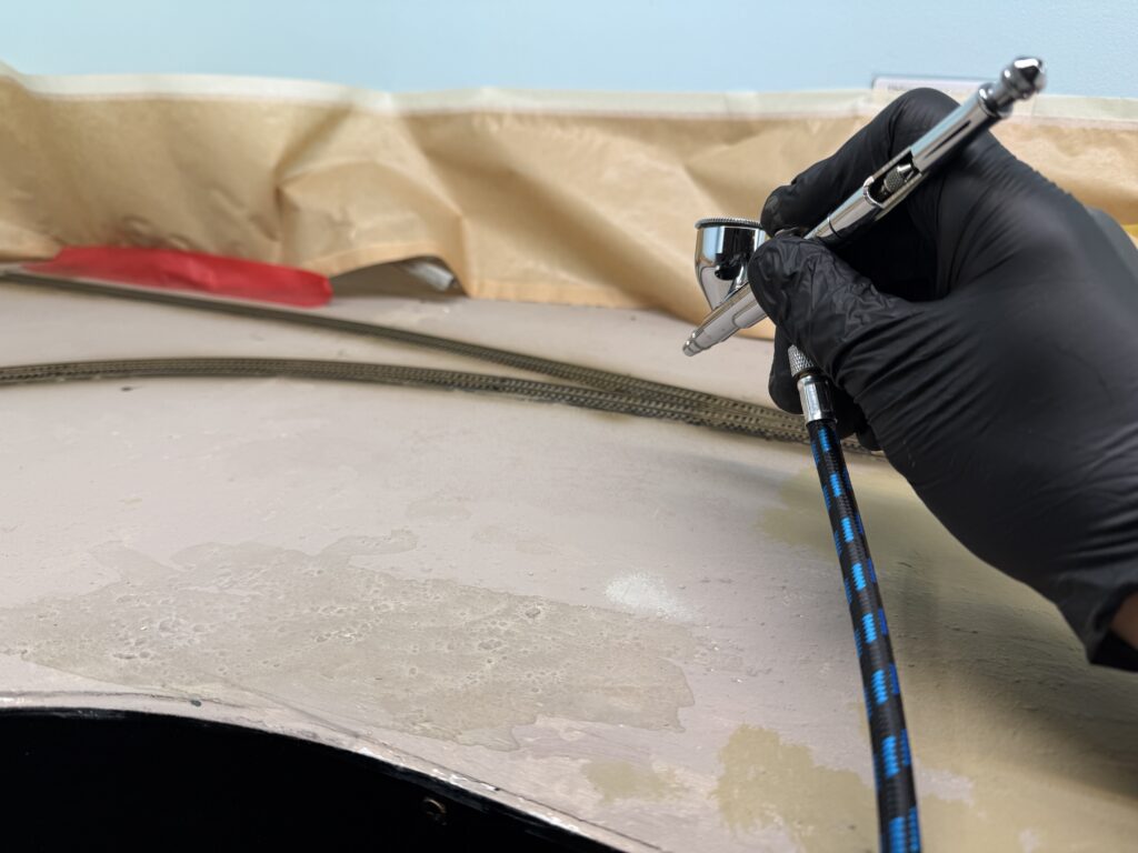
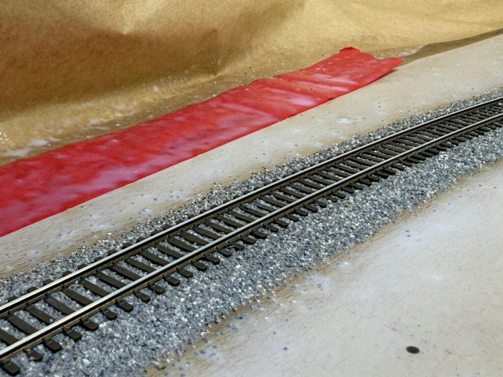
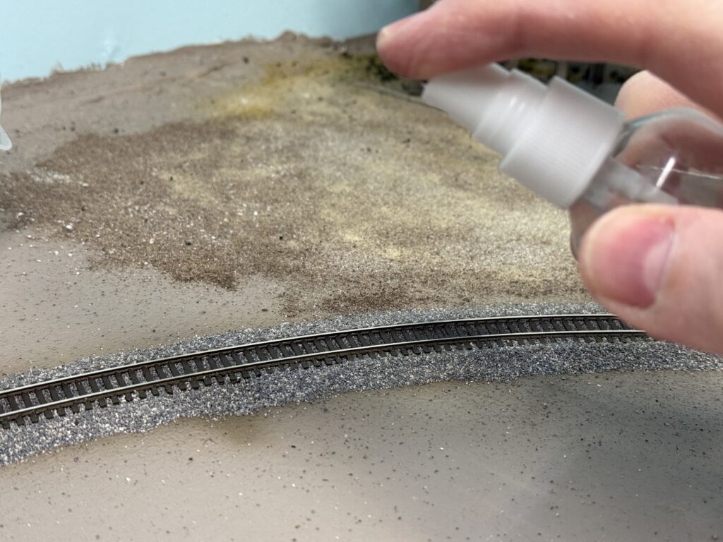
After the ballast was in place, I misted the tracks with a 40:60 mix of 99.9% isopropyl alcohol and water, letting it soak thoroughly. This helps break the water’s surface tension and allows the glue to penetrate the ballast. Once it was well soaked, I sprayed a 50:50 mix of water and Liquitex Matte Medium.

Track ballast misted with water and alcohol
Ballasted track

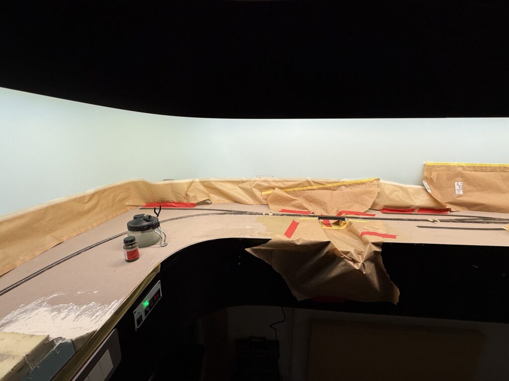
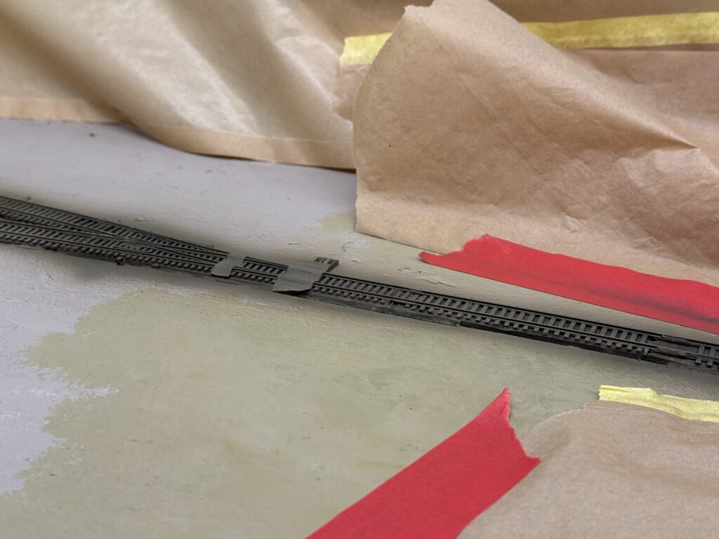
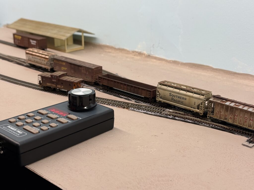
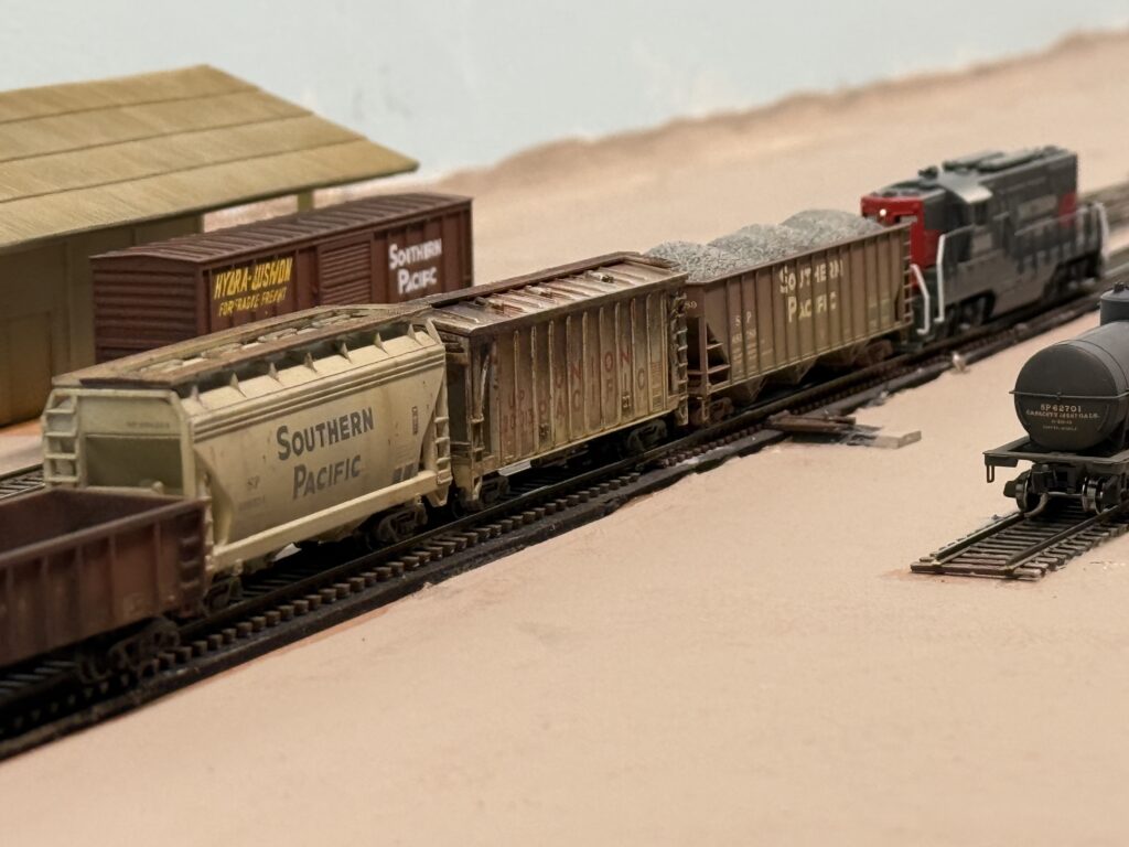
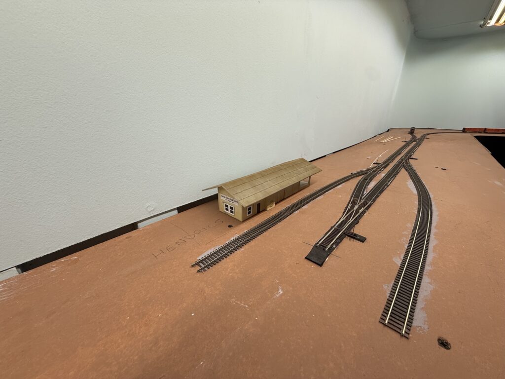
At the ConRock Ready-Mix Cement Plant, I used some tan terrain material to slightly bury the track and give it a more realistic, dirt-embedded look.

Track buried in dirt

Track Weathering

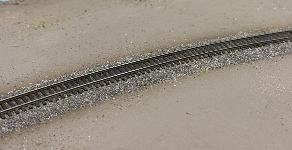
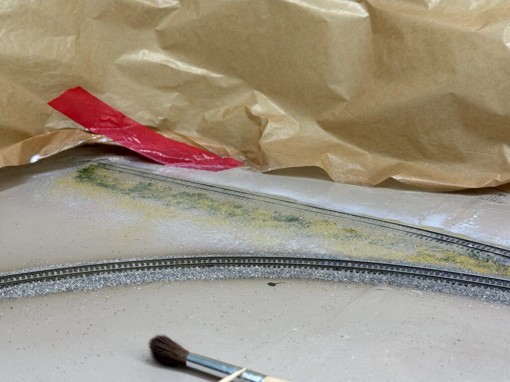
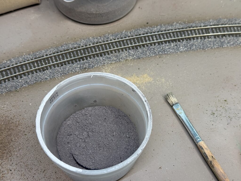
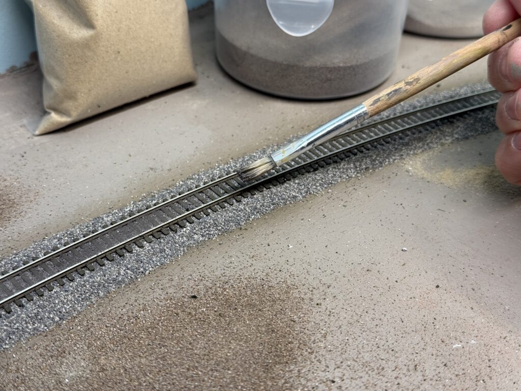
I weathered the area between the rails using a mix of plaster and black powdered pigments in a 2:1 ratio.

Weathering powder made of 2:1 plaster/black pigments

Then, I spread the mixture between the rails with a fairly stiff flat brush. Afterwards, I misted the area with water, which activated the plaster and sealed everything firmly in place.

Track ballast: weathering between the rails
Misting the weathering powder with water

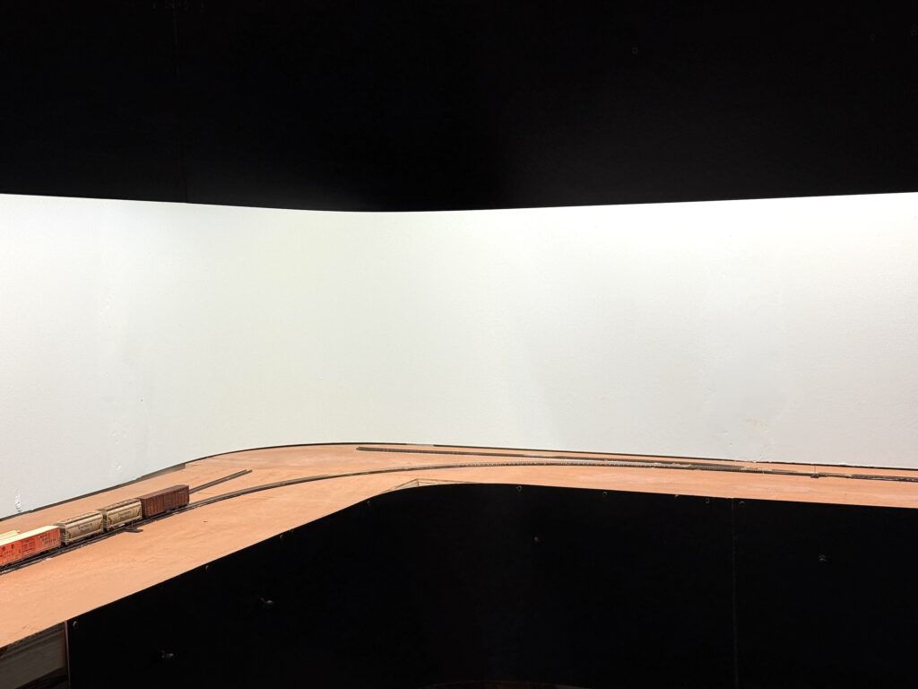
Here is a photo of the weathered track after the plaster of Paris and pigment mix had fully dried.

Weathered track

Paint the track

Before ballasting, I usually paint the track with a brown-gray color.

I found a fifteen-year-old bottle of Polly Scale Railroad Tie Brown that I had used on my previous SP Coast Line layout to paint the track.

Paint the track
Paint the track: masking

The paint had aged very well, so I was able to use it and airbrush it over all the tracks.

Paint the track with an airbrush

I masked the areas where the points hinge and where they touch the stock rails.

Masking the turnouts

Afterwards, I used a fine paintbrush to carefully paint the masked sections, making sure the paint did not interfere with electrical contact.

Track painted


A painted track makes a huge difference in the final appearance of a layout. Even a light coat of color immediately tones down the unrealistic shine of the raw plastic ties and the bright nickel-silver rails.

The Atlas code 55 ties, in particular, have a uniform brownish tone that looks toy-like until blended with a more natural brown-gray wash. Painting before ballasting gives the scene a visual foundation. Rails, ties, and ballast will later merge into a single, believable texture.

Once weathered and ballasted, the track will no longer stand out as a manufactured part, but rather blend seamlessly into the landscape, enhancing the realism of the entire scene.

Test Operating Session

Running a test operating session helps reveal whether the trackwork and car movements meet expectations.

It is always important to run a test operating session before painting and ballasting the track, since any minor or major issue can be addressed without damaging the scenery.

Test operating session

The first operating session was completed with the help of my seven-year-old son, who took the role of engineer. I printed a simple switchlist, and he performed all the switching under my guidance. We started from the staging yard, completed our setouts and pickups, and returned to staging in about one hour.

During the session, I discovered that my Atlas GP9 with an ESU sound decoder, purchased new in November 2024, had a serious gauge problem on the rear truck axles. I checked the wheels with two different tools: the official NMRA gauge and the Micro-Trains Line coupler gauge.

Even after correcting the axle gauge, the locomotive still derailed every time it passed through a crossover. I tested six other locomotives, and none of them had any issues. No matter how I fine-tuned the wheels, the GP9 kept derailing over the same turnouts.

I never had problems like this on my previous layout, which included about forty Atlas Code 55 turnouts. However, I must admit that the quality control of Atlas turnouts is not what it used to be twenty years ago.

I checked several against the NMRA gauge, and about eighty percent showed a narrow flangeway clearance. It is quite disappointing, especially that an Atlas locomotive struggles to run smoothly over Atlas track.

By the way, apart from a few hiccups with the GP9, the session once again proves that a layout with only seven turnouts can still be a lot of fun to operate.

Team track and Hendrick's Builder Supply spur
Controlling the train with a NCE throttle.
Test operating session

Layout Tour

An SP Burbank Branch in N Scale Layout Tour Video

Here is a layout tour right after I completed the three-track staging yard by laying the track and wiring all the feeders to the DCC bus.

Since the staging turnouts are operated with Caboose Industries ground throws, I also installed a frog juicer to power the frogs.

The three staging tracks are more than enough to cope with the Burbank Branch in N scale layout traffic. See the trackplan for more details.

First Running Test

First running test on the SP Burbank Branch in N scale switching layout.

After completing 90% of the trackwork, I performed a first running test to check the work done so far. Turnouts were of course under close examination. A few spots revealed two things:

  • Atlas code 55 turnout quality control isn’t perfect. In a few cases, the guard rails were slightly too close to the stock rail, as confirmed with an NMRA gauge.
  • I need to check the wheelset gauge on a few locomotives, as they don’t appear to have been set correctly at the factory. I’ll be using an NMRA gauge for this.

Video

Overall the test went well, and I was able to simulate a short switching operating session.

It’s essential to get reliable operations on a layout, especially in smaller scales like N. The first test run offered valuable insight into both track and rolling stock performance.

While a few adjustments are still needed, it’s encouraging to see the layout begin to function as intended. With minor fine-tuning, the SP Burbank Branch will soon be ready for smooth and reliable operations.

Scratchbuilding a structure

Step-by-step on scratchbuilding a structure with styrene

I had wanted to embark into scratchbuilding a styrene structure for years but never did it properly. This time, I decided to model the Hendricks Builders Supply Company in Lankershim/North Hollywood.

Lankershim/North Hollywood Station Lankershim / North Hollywood Station

This structure will be placed on the layout according to the trackplan.

Drawing

I started by drawing a rough plan on millimeter graph paper.

Project drawing of the Hendricks Builders Supply Company structure

I used Evergreen styrene 4041 clapboard 1mm (.040″) sheets for the main walls.

Using Evergreen clapboard sheets.

Windows

I had some doors and windows on hand that matched the building’s style.

Door opening cut

Using a nibbler tool, I cut out the door openings from the wall.

Nibbler tool used for the door opening

Then, using a small file I refined the door and window openings.

Scratchbuilding a structure needs some filing to refine the door openings

Test-fitting a window.

Test-fitting the windows

Gluing

The four main walls are ready to glue. I reinforced each corner with 2.5 mm Evergreen 175 styrene strips for stability.

Reinforcing the internal walls, ready to assemble

I used Tamiya Cement to glue the parts.

4 walls assembled and glued in place

Two 2.5 mm strips also reinforce the middle of the structure.

Scratchbuilding a structure requires some internal reinforcements

I made the wooden door from clapboard styrene sheet and glued it inside the wall. On the outside, I added vertical styrene strips for detail. For smaller pieces, I used Tamiya Extra-Thin Cement.

Wooden door made of clapboard styrene sheet

To strengthen the loading platform, I inserted reinforcement strips underneath.

Load platform reinforcements
Platform assembled

Then, I glued the platform to the main structure.

Scratchbuilding a structure. Loading platform glued to the main structure

Before adding the roof, I reinforced the center with a triangular styrene piece.

Scratchbuilding a structure: reinforcing the roof supports

Scratchbuilding a structure: Lighting

I wanted interior lighting, so I mounted a warm-white LED onto a small styrene support.

Scratchbuilding a structure: using an LED to light the structure
Warm-white LED installed
Scratchbuilding a structure: lighting

Roof

Then, I installed the roof. I used Vallejo Plastic Putty to fill a few gaps in the roof joint.

Roof added and Vallejo Plastic Putty used to fill gaps
Scratchbuilding a structure: roof added.

I spray-painted the interior walls black to prevent light from bleeding through the thin styrene.

Interior walls spray-painted black

Scratchbuilding a Structure: Painting

I painted the roof with a few shades of Vallejo gray paint, and the walls with Vallejo Aged White (71.132).

Walls painted Vallejo Aged White

Stratchbuilding a Structure: Weathering

I started weathering the walls by applying a dark brown acrylic wash.

Next, I added more streaks of brown paint to weather the roof.

Then, I glued the windows and the door in place. I used products made by the German firm Auhagen.

Windows glued

I added a piece of clear plastic to the inside of the windows.

Clear plastic for glass.

Next, I applied the “Hendricks Builders Supply” sign on the structure side.

Scratchbuilding a structure: Hendricks Builders Supply Company

Here is a test-fit on the final location on the Burbank Branch in N scale layout.

Hendricks Builders Supply Company structure
Hendricks Builders Supply Company structure.

Scratchbuilding a structure has been a rewarding project. While I had scratchbuilt a few simple structures before, this is the first time I completed a slightly more complex one.

The structure is not a perfect replica of the real thing; however, it works well as a rail-served industry and adds to the visual experience during operating sessions.

Adding a Fascia to the Layout

Adding a fascia to the layout for a neat look.

Adding a fascia gives the layout a clean, finished appearance. It also frames the scene and hides wiring underneath. The fascia also gives me a place to mount toggles and labels without cluttering the scene. I kept the design simple, just enough to tidy up without overcomplicating things.

Adding Fascia to the Layout

Toggle switches for turnouts are mounted near the turnout they control, making access easier and the track plan more intuitive. I designed a recessed mount for the toggle switch, which I plan to 3D print and install behind the fascia.

The recessed controls help keep the fascia flat and avoid accidental bump or damage during operating sessions.

Turnouts toggle switches
3D print drawing for a recessed toggle switch mounting plate.

I use Autodesk Fusion for 3D drawings. The personal edition is free for non-commercial use.

Power District Reset Button

I also installed red LEDs – one for each DCC power district – along with a push-button to reset the power breakers after a short.

Adding a Fascia to the Layout: power breaker LED and reset push-button.

I’ll fill the gaps in the curved section of the fascia with precisely cut extruded foam board.

NCE UTP Panels

Next, I measured and cut an opening for the NCE UTP panels, where the throttles will connect. Then, I used a Dremel with the appropriate bit to make the cut cleanly.

Laser level measurement for the NCE UTP Panels
I used a Dremel to cut the opening.

I refined the opening with a rasp. Then, I drilled four pilot holes for the NCE mounting plate.

NCE UTP Panel opening cut and refined.

The image below shows the NCE UTP Panel installed from the inside of the fascia.

NCE UTP Panel installed
Adding a Fascia to the Layout: Panel installed and NCE ProCab throttle connected

In the end, the fascia helps the layout feel finished, even while things are still in progress. It’s a small touch, but it goes a long way toward visual consistency and reliability.

The fascia adds both function and polish to the layout. Therefore, it hides clutter and supports controls. In addition, it frames the scene beautifully. I installed toggles and panels cleanly and efficiently. As a result, the layout looks more finished and cohesive, and overall operations feel easier and more enjoyable.