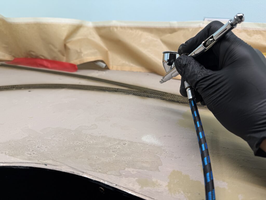
Before ballasting, I usually paint the track with a brown-gray color.
I found a fifteen-year-old bottle of Polly Scale Railroad Tie Brown that I had used on my previous SP Coast Line layout to paint the track.
The paint had aged very well, so I was able to use it and airbrush it over all the tracks.
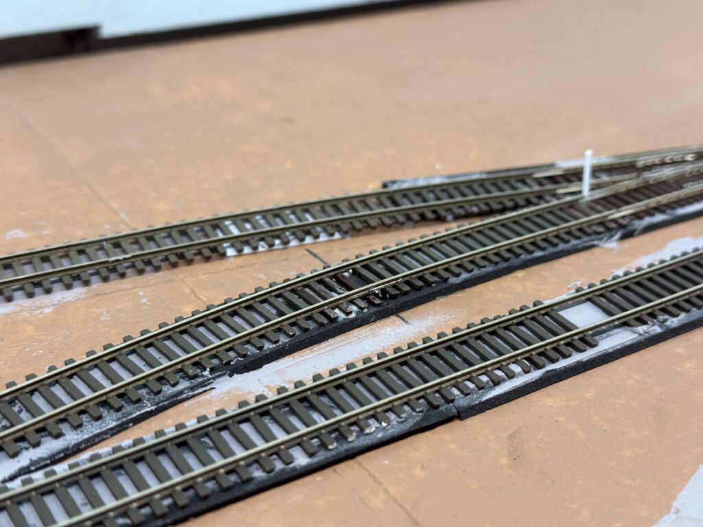
I masked the areas where the points hinge and where they touch the stock rails.
Afterwards, I used a fine paintbrush to carefully paint the masked sections, making sure the paint did not interfere with electrical contact.
A painted track makes a huge difference in the final appearance of a layout. Even a light coat of color immediately tones down the unrealistic shine of the raw plastic ties and the bright nickel-silver rails.
The Atlas code 55 ties, in particular, have a uniform brownish tone that looks toy-like until blended with a more natural brown-gray wash. Painting before ballasting gives the scene a visual foundation. Rails, ties, and ballast will later merge into a single, believable texture.
Once weathered and ballasted, the track will no longer stand out as a manufactured part, but rather blend seamlessly into the landscape, enhancing the realism of the entire scene.
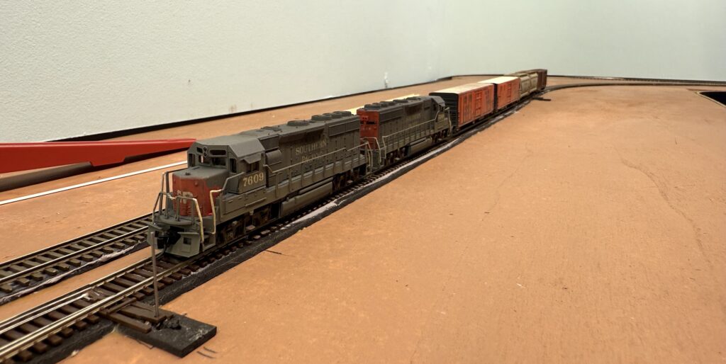
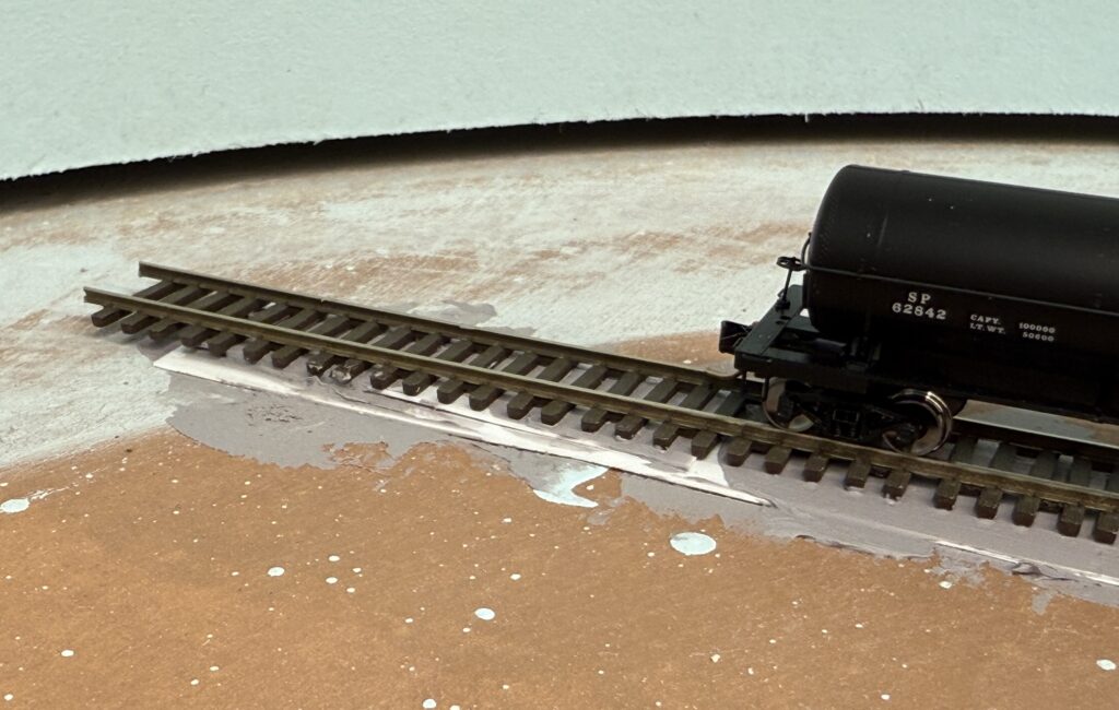
First running test on the SP Burbank Branch in N scale switching layout.
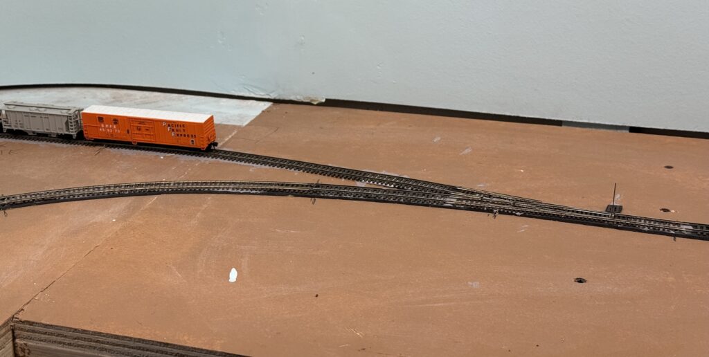
After completing 90% of the trackwork, I performed a first running test to check the work done so far. Turnouts were of course under close examination. A few spots revealed two things:
Atlas code 55turnout quality control isn’t perfect. In a few cases, the guard rails were slightly too close to the stock rail, as confirmed with an NMRA gauge.
I need to check the wheelset gauge on a few locomotives, as they don’t appear to have been set correctly at the factory. I’ll be using an NMRA gauge for this.
Video
Overall the test went well, and I was able to simulate a short switching operating session.
It’s essential to get reliable operations on a layout, especially in smaller scales like N. The first test run offered valuable insight into both track and rolling stock performance.
While a few adjustments are still needed, it’s encouraging to see the layout begin to function as intended. With minor fine-tuning, the SP Burbank Branch will soon be ready for smooth and reliable operations.
Trackwork fine tuning: adding both visual and operational details to N scale code 55 tracks.
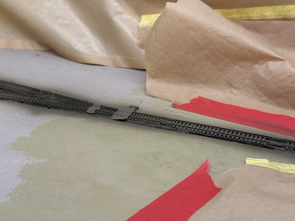
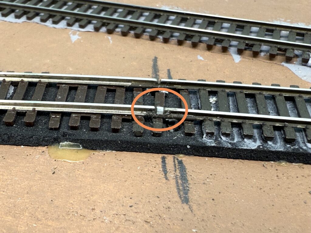
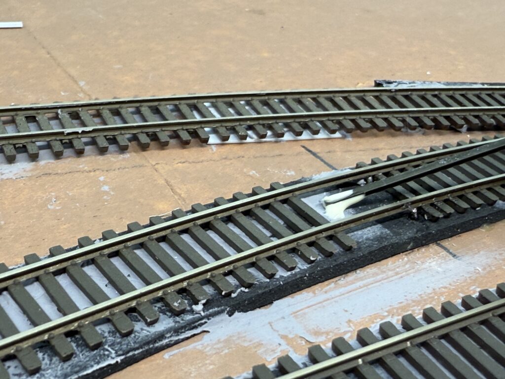
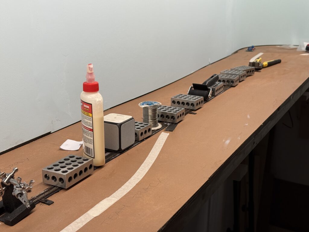
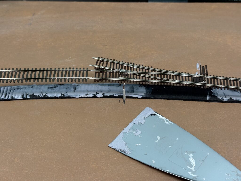
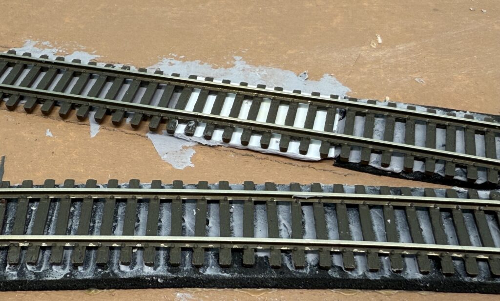
Trackwork fine tuning is crucial for reliable operations. This is especially true in N scale. I added small pieces of styrene to fill gaps at rail joints, helping wheels roll smoothly. The styrene is fixed in place with CA glue, then carefully carved to shape with a sharp hobby knife.
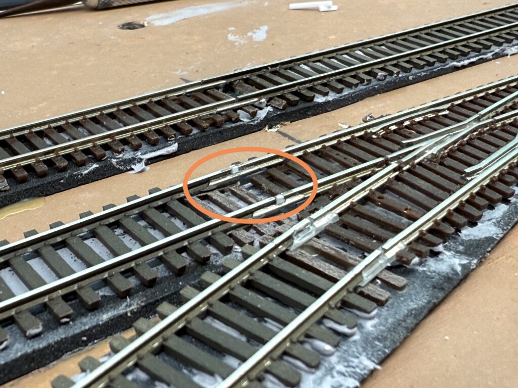
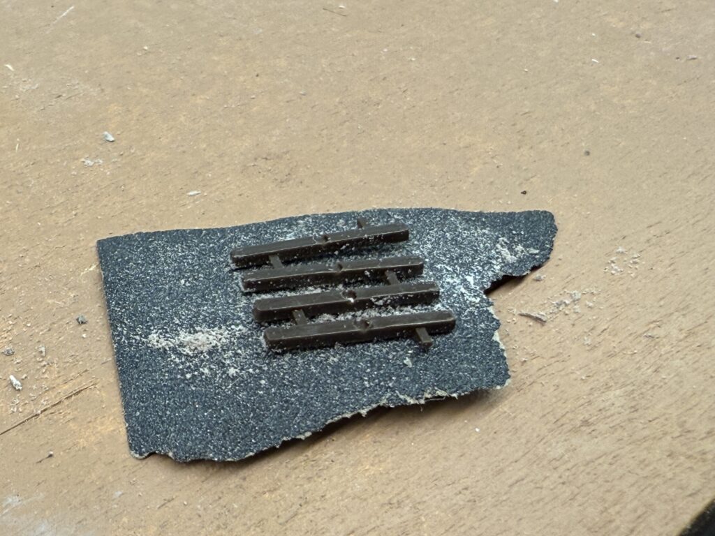
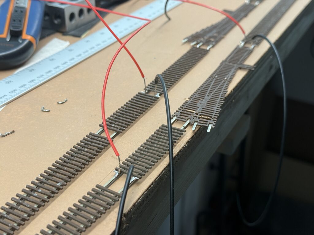
I also replaced the ties I had removed when soldering feeders to the underside of the rails. In the photo, you can see sections where ties were temporarily removed for easier soldering.
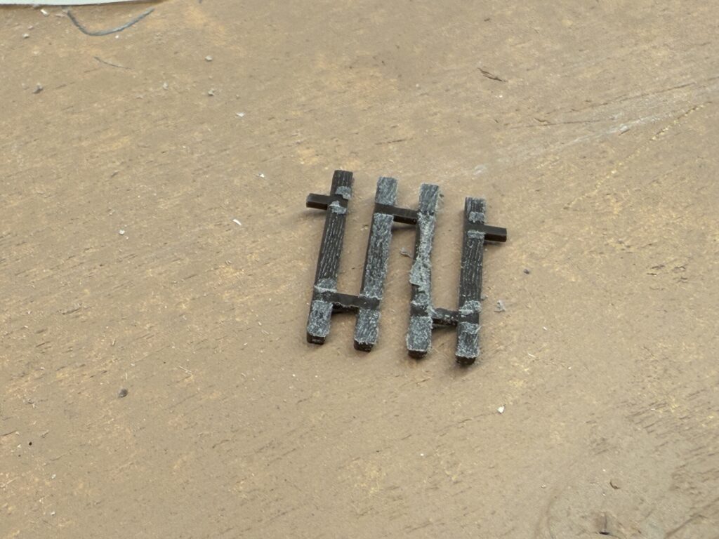
First, I sanded the ties to remove the molded spike details. I laid a sheet of sandpaper on a flat surface and rubbed the ties across it.
Once the spikes were gone, I test-fitted the ties under the rails.
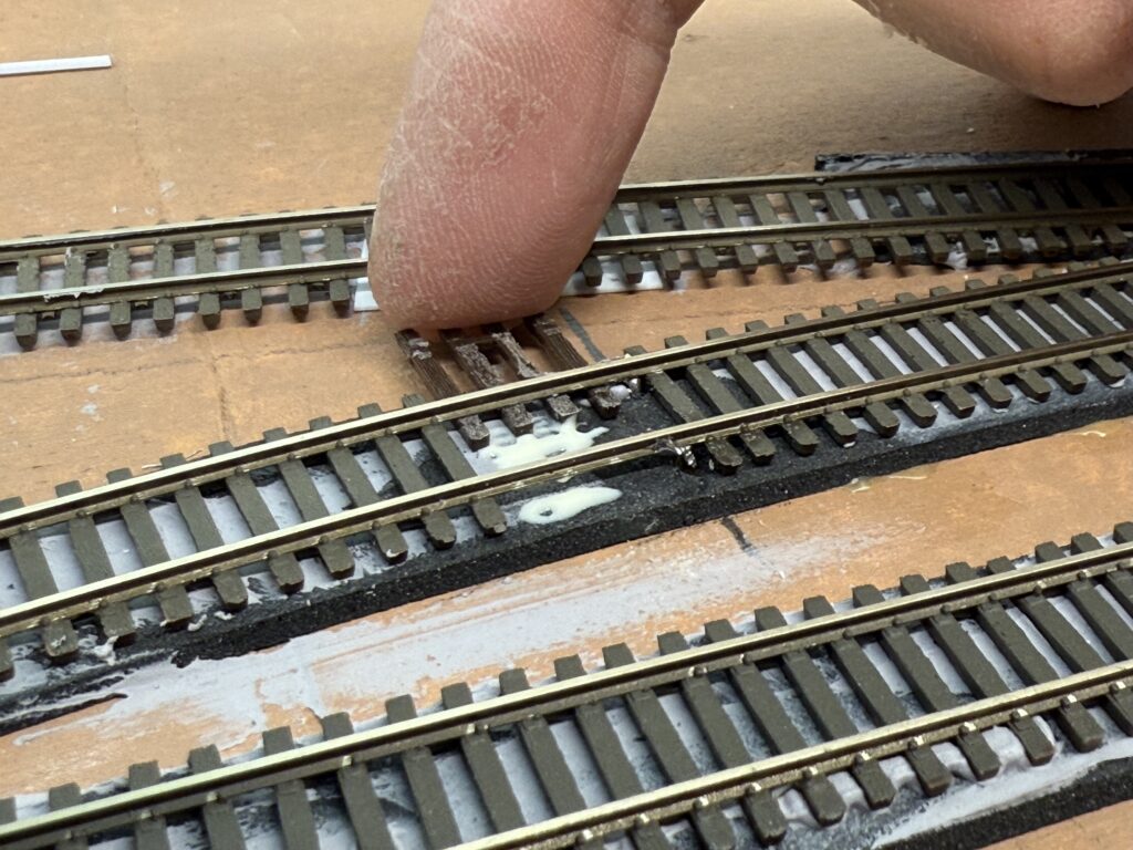
Then I applied a few drops of Titebond glue and slid the ties into place, adjusting the position as needed.
Once painted and ballasted, these small fixes will be barely noticeable.
These small improvements may seem minor, but they make a big difference in how smooth trains run. On an N scale switching layout, reliable operations depend on well-prepared trackwork and solid electrical connections.
Nothing ruins the flow of a session like derailments or stalling at a poorly aligned joint. Paying attention to these details brings your layout closer to realistic railroad performance.
Clean solder joints and neatly replaced ties also enhance the visual appeal of your track. Each detail you refine adds to the overall reliability and realism of your scene.
Good trackwork is the backbone of stress-free operations. Investing time early pays off later when the layout runs smoothly without surprises. For N scale, especially, precision matters – both for looks and reliable running.
Final steps with laying tracks on the SP Burbank Branch N scale layout
The final steps of laying tracks is one of my favorite aspect of the hobby. It’s when the layout starts to take shape, and the first test operations can take place. At this point all trackwork is done, but the staging and the LA River bridge.
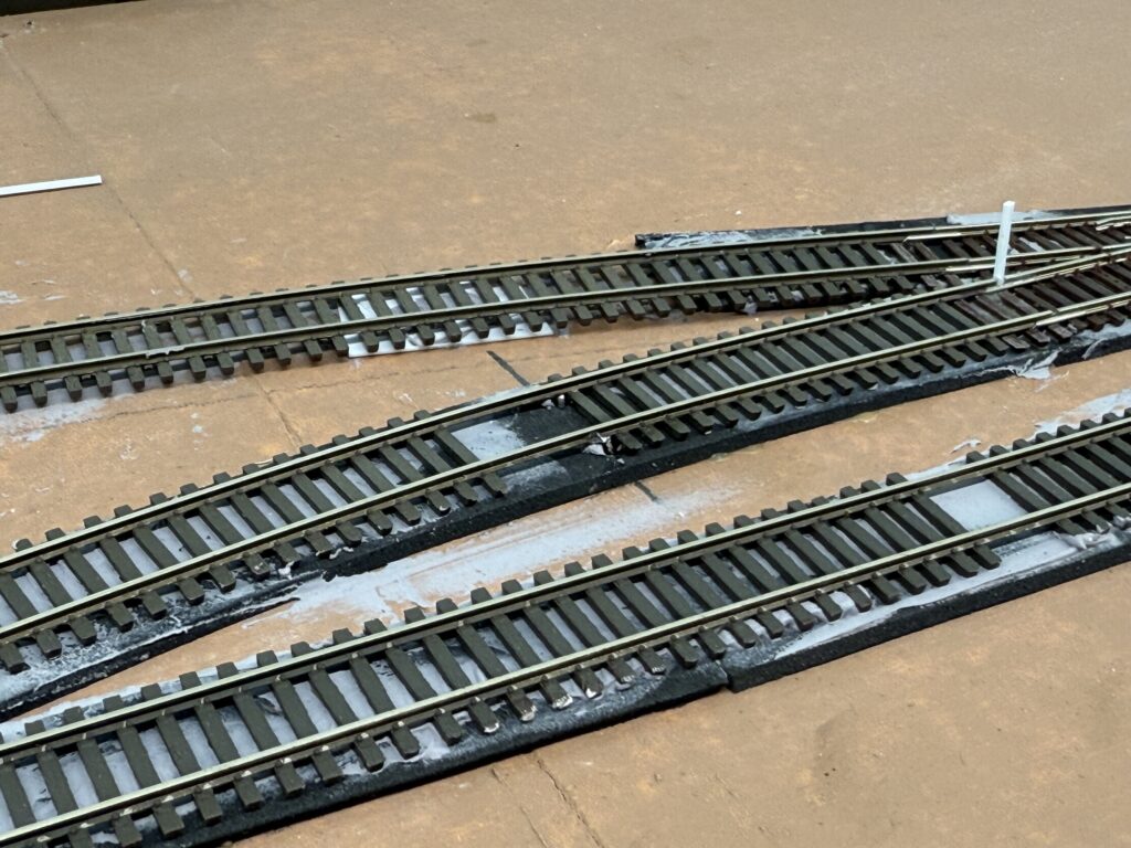
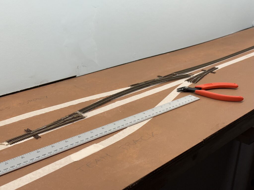
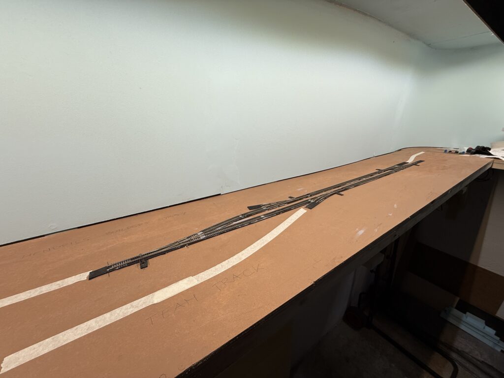
I finished laying track for the spurs, here pictured are the Team Track and Hendrick’s Builders Supply.
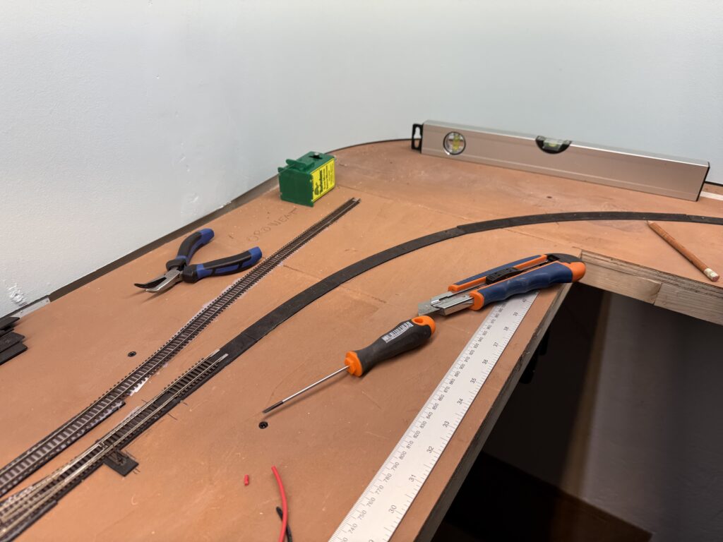
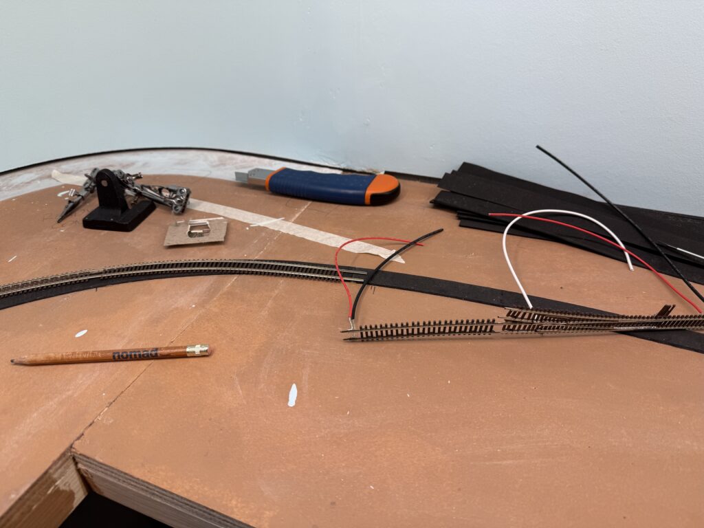
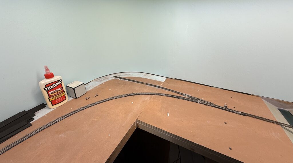
Then, I laid the curve on the west end of the layout – near the Oroweat Bakery and Terry Lumber spurs. First I test-fit the curve.
Then I laid EVA foam roadbed.
Then I laid track and connected the feeders, soldered under the rails.
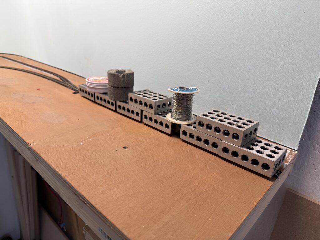
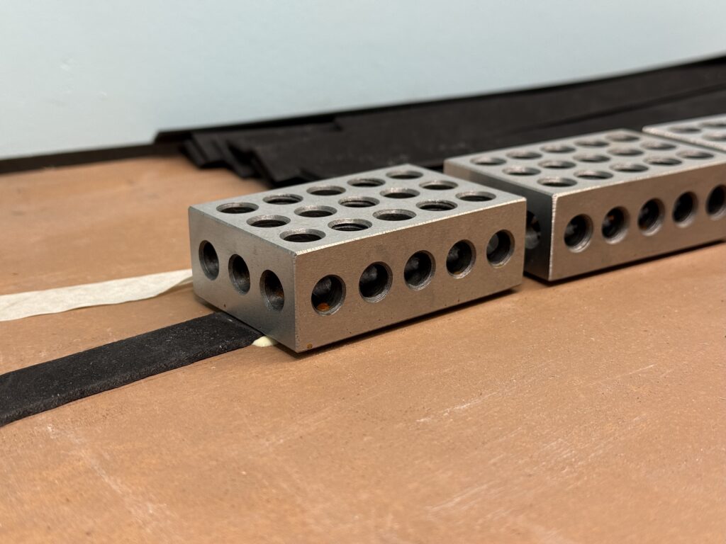
I used metal weights to hold the track firmly in place while the glue dried.
Staging
While the removable (foldable) staging isn’t ready yet, I started figuring out the mechanical connection. I screwed two brass screws into the roadbed and plywood subroadbed, then soldered the rails right on top of them.
This should keep the track from shifting and create a solid connection between the layout and the foldable staging yard.
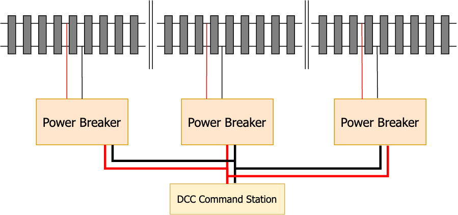
Power Breakers
Each section of flextrack and each turnout have their own feeders. I also divided the layout into three separate DCC districts, each managed by an NCE EB-1 Electronic Breaker.
Should a short circuit occur in one power district, its dedicated power breaker would cut power to that district, while the other two would remain operational
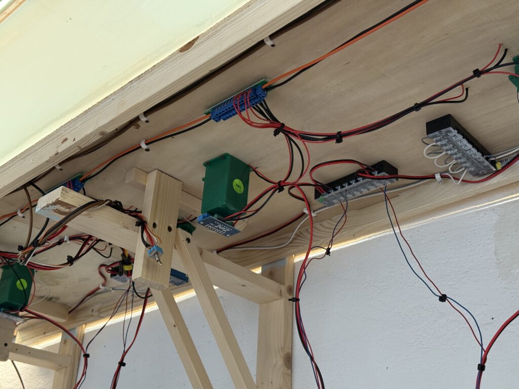
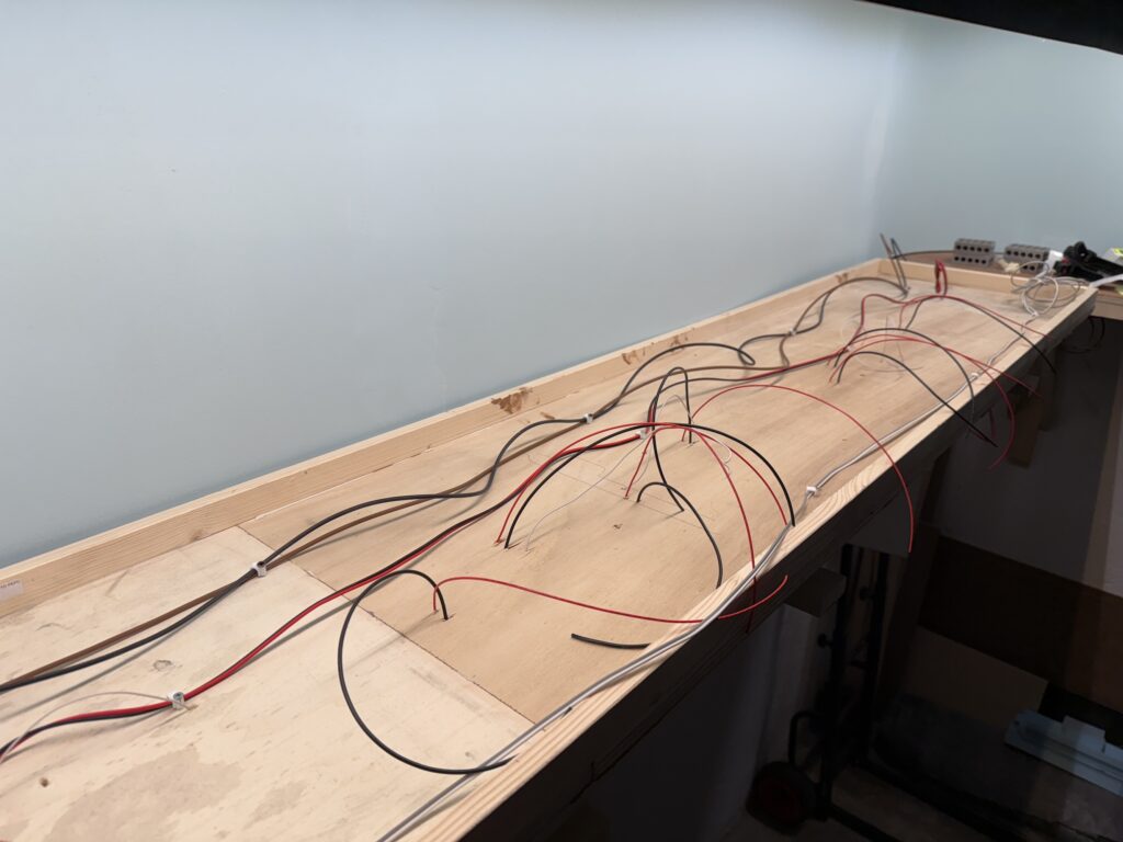
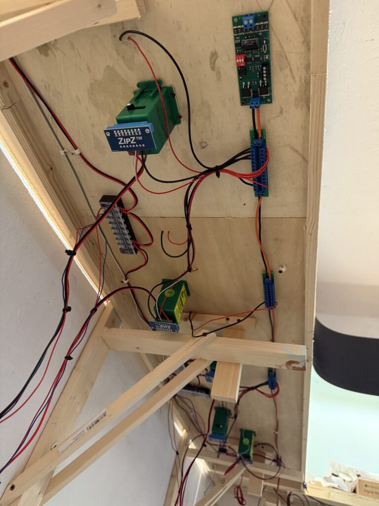
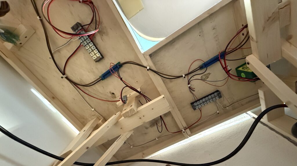
Wiring
Keeping wiring tidy and well-organized is crucial for troubleshooting. I’ve connected LEDs to each power line – for the Tortoise switch machines and the layout lights – by screwing them onto the terminal connectors. This allows me to instantly see if a section loses power.
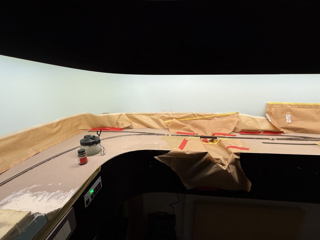
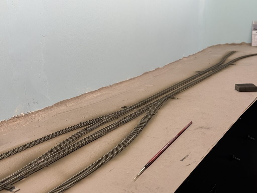
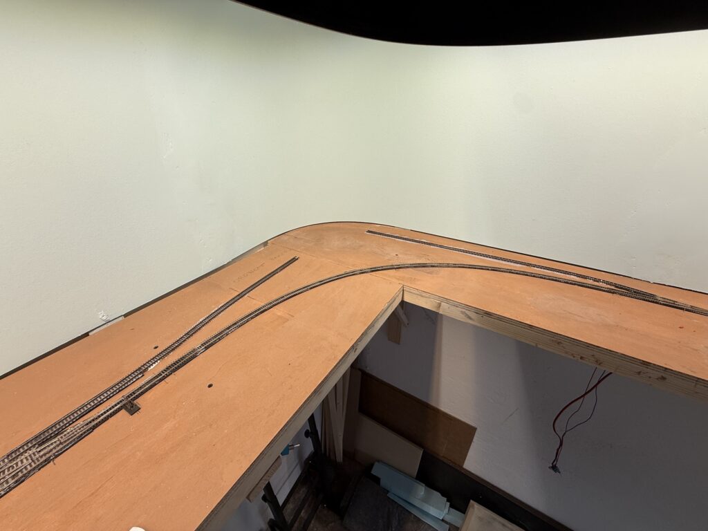
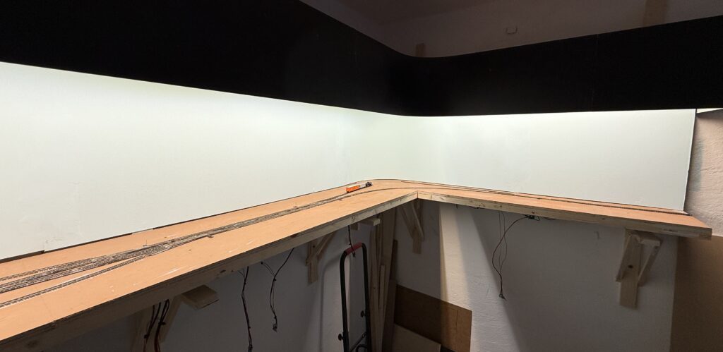
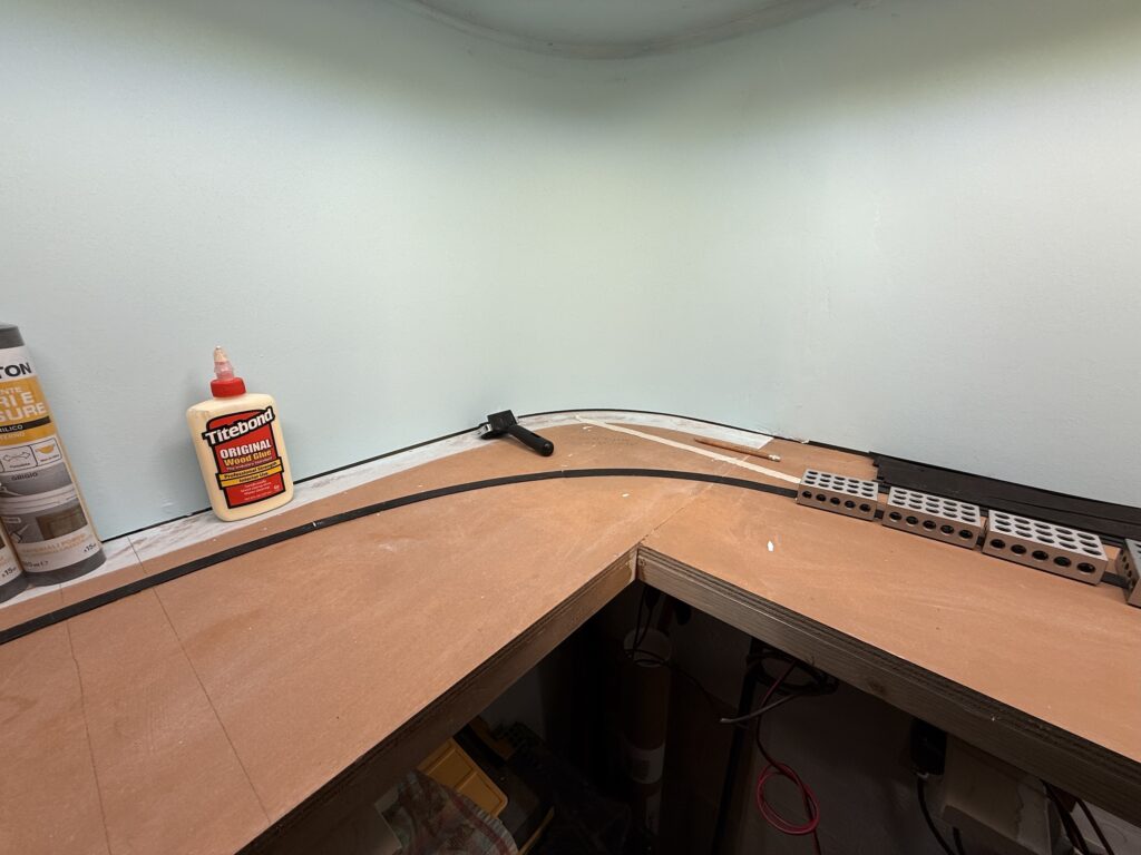
Laying Tracks Final Steps
Here’s a panoramic view of my N scale switching layout with the track laid so far. Next step is to install the LA River section with its bridge and connect the missing piece of flextrack.
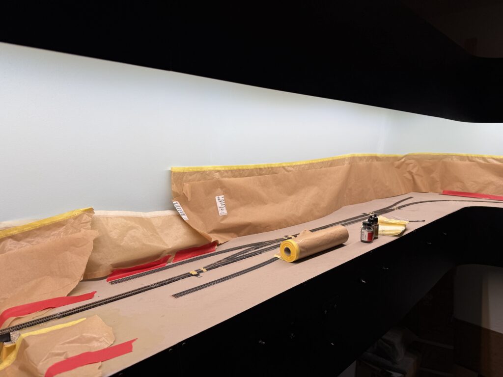
West-end of the layout.
East-end of the layout.
After that, I’ll assemble and install the foldable staging yard.
I started test-fitting Atlas Code 55 turnouts and Micro Engineering Code 55 flextrack. I had used this combination on a larger N scale SP layout, and it worked well.
Unlike previous projects, I bought a Xuron cutter this time – specifically the 2175B model, which also suits N scale track.
I used to cut rail with a Dremel and cutting disk, but the Xuron cutter feels much more comfortable.
While waiting for the EVA foam roadbed glue to cure, I soldered feeders to the rails using a 15W soldering iron and rosin core flux.
To make wiring easier, I flipped the base upside down. It isn’t screwed to the benchwork yet, so this was simple.
Next, I glued the track to the roadbed using a thin layer of acrylic caulk.
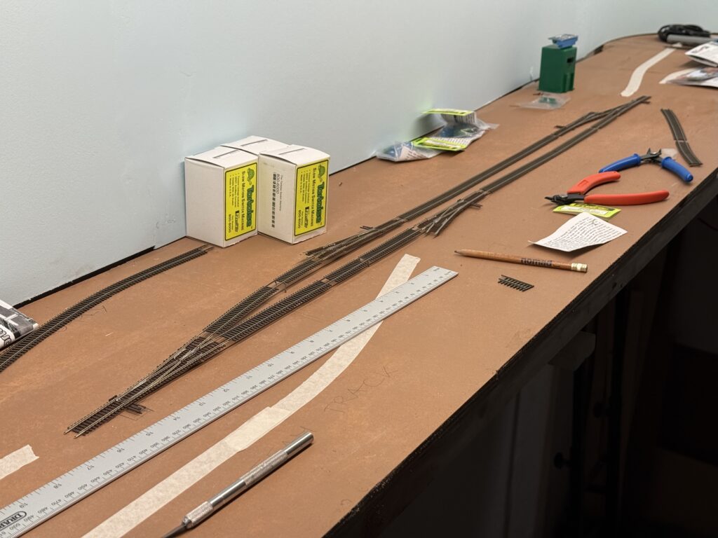
The main line and sidings are now in place. I’ll lay the spurs for Hendrick’s Supply Builders, Oroweat Bakery, and the Team Track next.
The team track will be wired through a DPDT switch, so it can also serve as a DCC programming track.
I used terminal strips and cable ties to organize the wiring. The wires hanging under the layout connect to the DPDT switches that control the Tortoise switch machines.
Then, these switches will be mounted on the fascia.
Wiring and laying tracks on a small switching layout requires planning, patience, and flexibility. Each step builds the foundation for smooth operations later on.
Using the right tools and techniques helps avoid frustration and saves time. As the layout grows, keeping things neat and modular makes future changes much easier.
With the basics in place, I’m excited to shift focus to detailing and fine-tuning operations.
I started laying tracks across most of my N scale layout. When needed, I flipped the plywood base upside down to handle wiring and install the Tortoise switch machines more comfortably.
Roadbed
To start, I used 2mm EVA foam strips for the roadbed. I glued them down with Titebond Original Wood Glue. For simplicity and a prototypical look, I laid the roadbed only under the mainline. Sidings and spurs will go directly onto the plywood.
Laying Tracks and Wiring
Next, I soldered 24AWG feeders to the underside of the rails. I drilled holes through the roadbed to connect the feeders to the DCC bus.
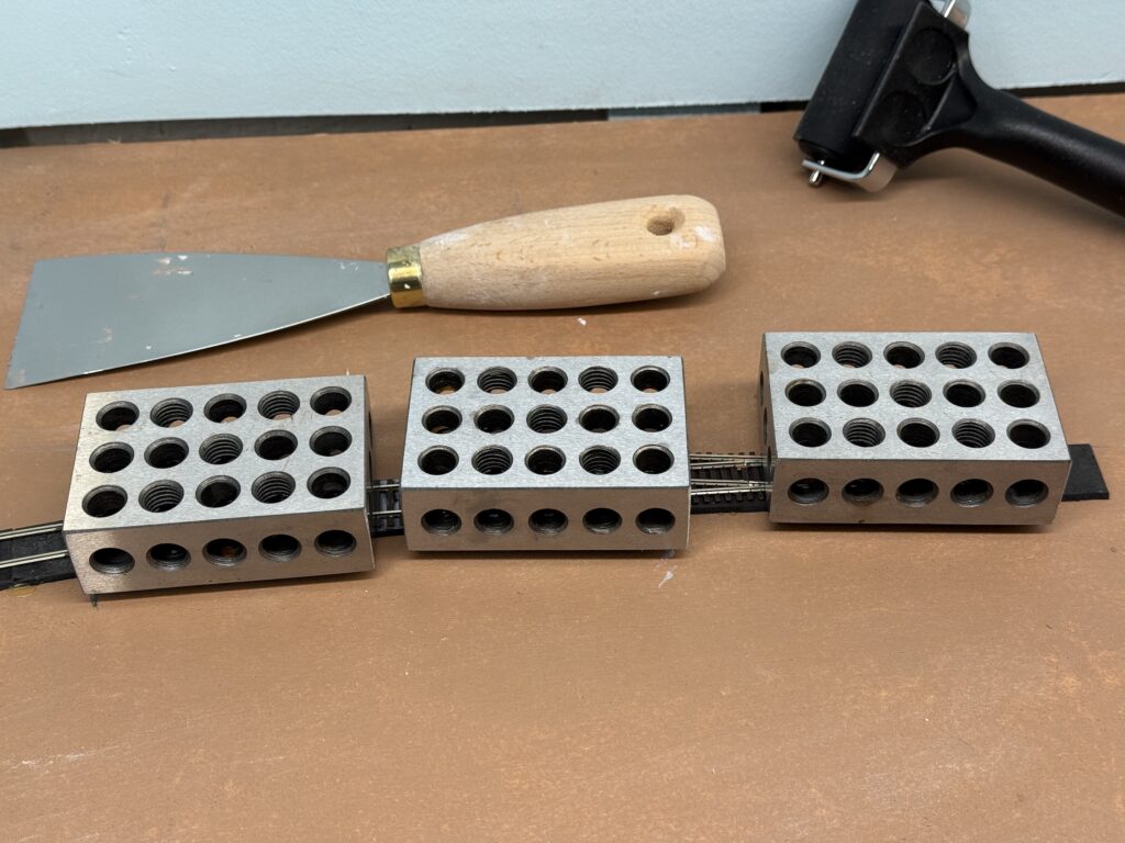
To secure the track, I applied a thin layer of acrylic caulk using a putty knife. I then placed metal blocks on top to hold the rails in position as the caulk dried.
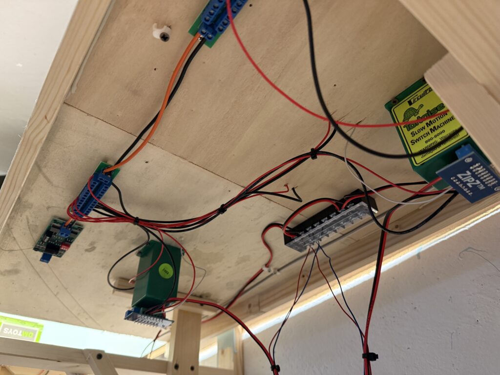
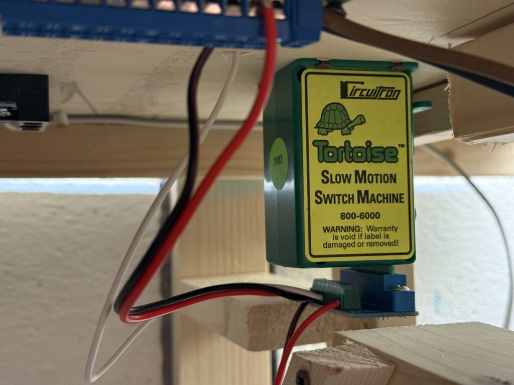
Switch Machines
Once the track was down, I flipped the base again to install the Tortoise switch machines. I also connected the feeders and ran the DCC bus wires.
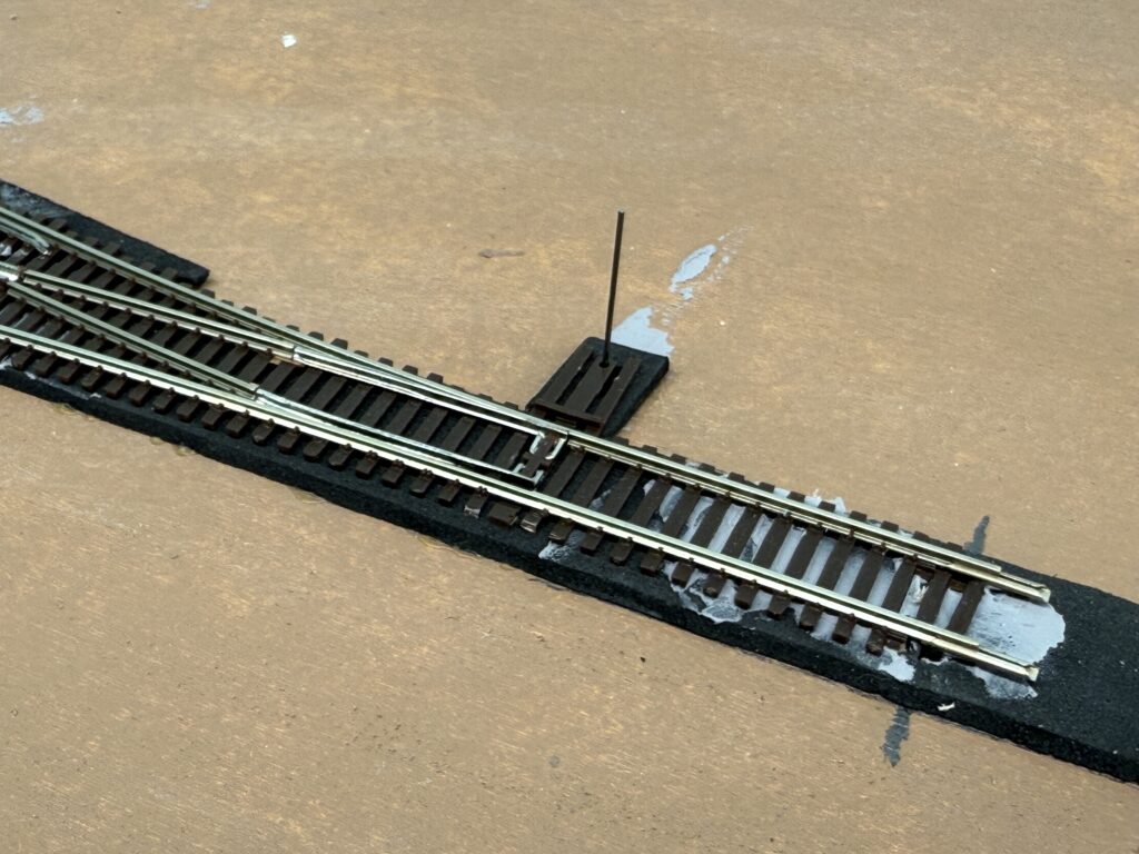
Afterward, I inserted the piano wire into the hole in the turnout’s throwbar.
I then screwed the switch machine to the plywood base and connected it using ZipZ solderless connectors.
Each Tortoise is controlled by a DPDT toggle switch and powered by a 12V DC supply
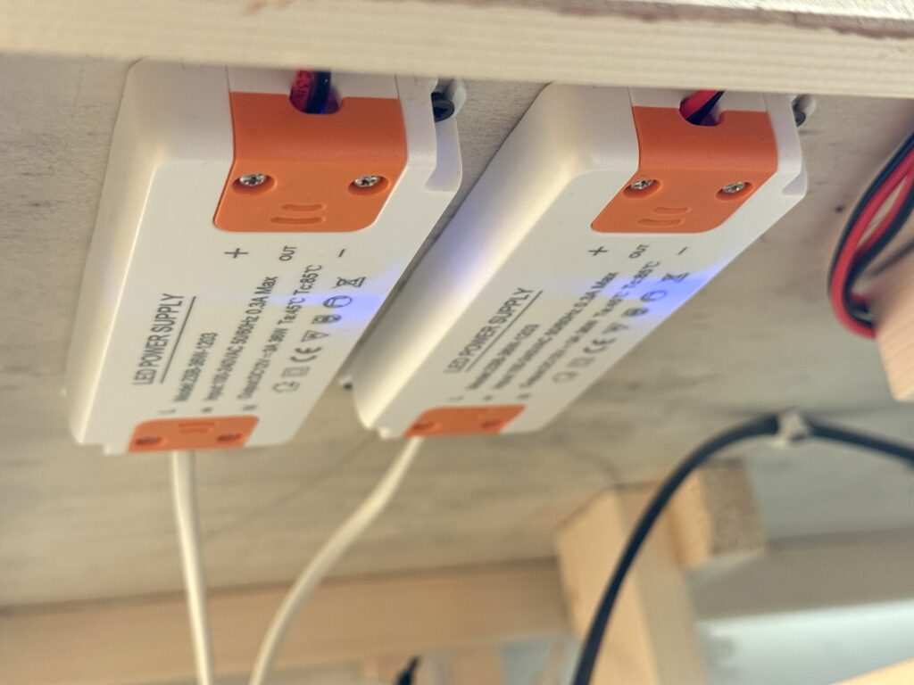
Power Supply
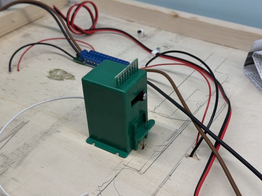
I installed two 3A 12V DC power supplies under the layout – one for the switch machines, and the other for layout lighting. This includes LEDs in buildings, vehicles, and streetlights.
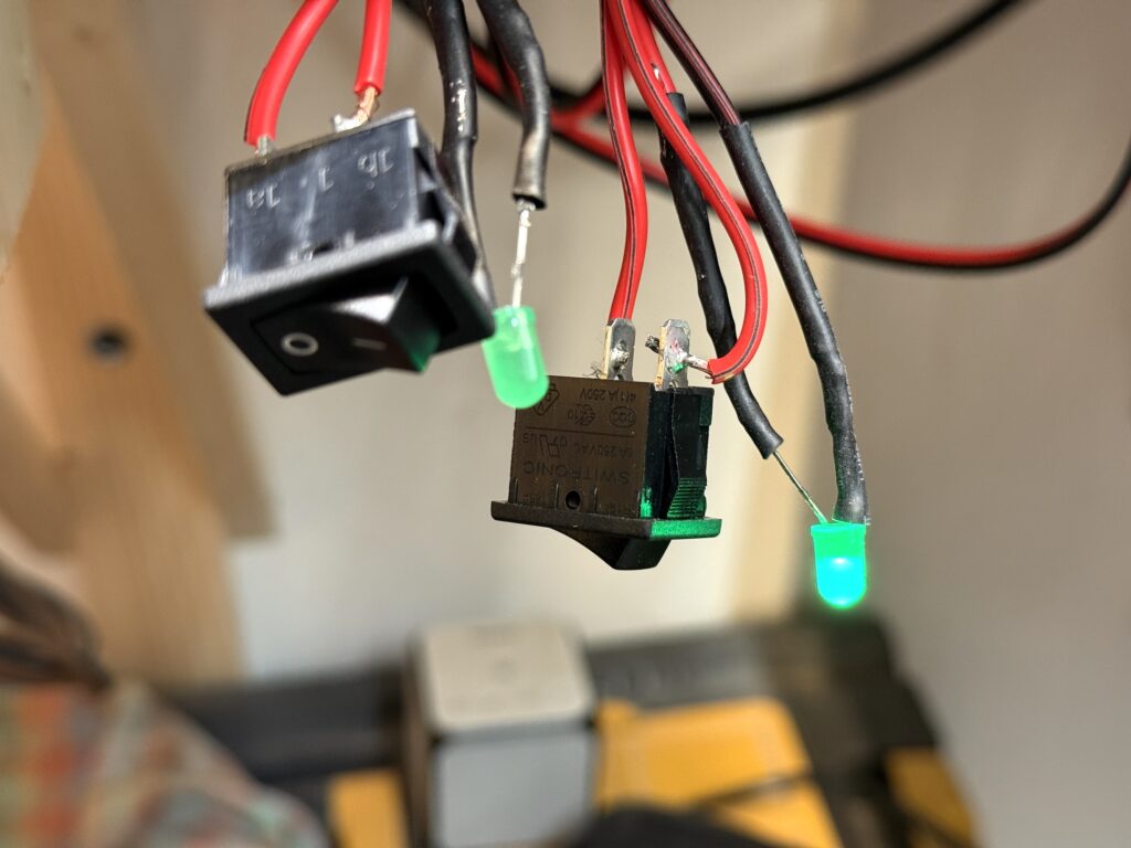
To monitor power delivery, I added a main switch to each 12V output. These switches illuminate an LED when active. I’ll mount both switches and LEDs on the fascia for easy access.
Trackwork Fine Tuning
The first section of tracks on my N scale layout is complete. Track has been laid, wiring is done and the first turnout is controlled by a properly installed Tortoise switch machine.
Here is the Conrock and Skyline ready-mix concrete spur.
I used thin pieces of styrene to shim tracks. One for the transition in track height from mainline (photo below, bottom) to the Conrock spur (photo below, top), and another one at the end of the same spur to keep the track level.
Wiring should be neat and well-organized to make troubleshooting easier if problems occur. Here is how I managed wiring on the Burbank Branch in N scale.
The trackwork phase marks a major milestone in building the layout, which is now coming together with solid progress.
Careful planning now will ensure smoother operations and fewer issues later and sets the foundation for future scenery and detailing.
We use cookies to ensure that we give you the best experience on our website. If you continue to use this site we will assume that you are happy with it.
You can revoke your consent any time using the Revoke consent button.