Category: DCC

Wiring and Laying Tracks

Wiring and laying track on the SP Burbank Branch in N scale

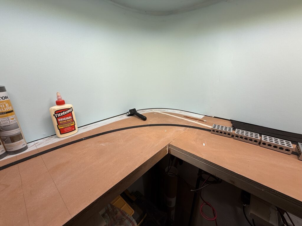
After completing wiring and laying tracks on the first section of my N scale switching layout, I continued extending the trackwork.

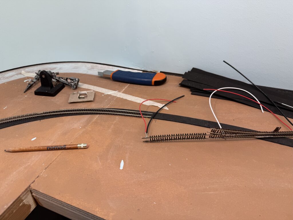
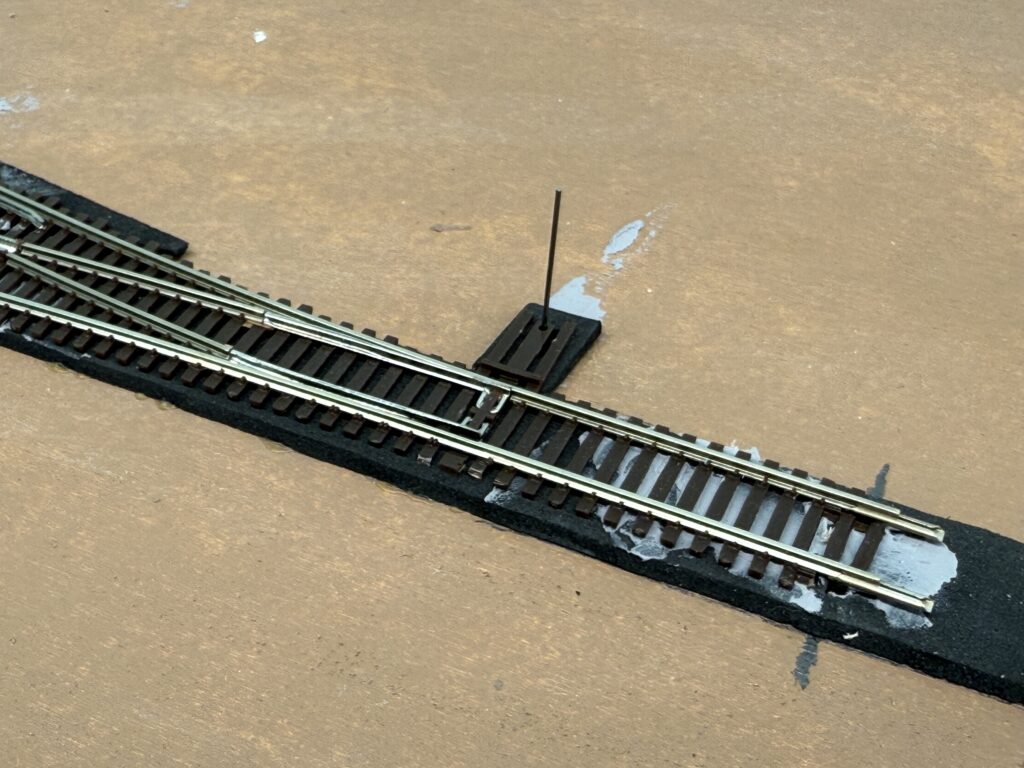
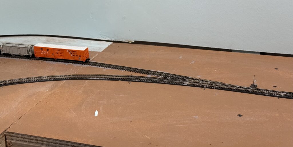
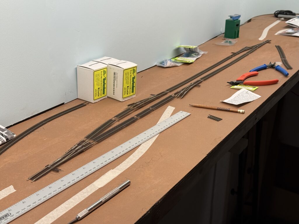
I started test-fitting Atlas Code 55 turnouts and Micro Engineering Code 55 flextrack. I had used this combination on a larger N scale SP layout, and it worked well.

Test-fitting the Atlas code 55 turnouts and Micro-Engineering code 55 flextrack.

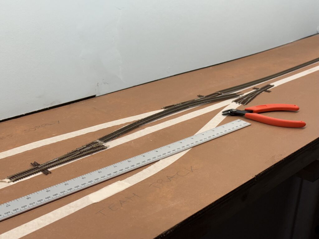
Unlike previous projects, I bought a Xuron cutter this time – specifically the 2175B model, which also suits N scale track.

I used to cut rail with a Dremel and cutting disk, but the Xuron cutter feels much more comfortable.

Wiring and Laying Tracks: Test-fitting the Atlas code 55 turnouts and Micro-Engineering code 55 flextrack.

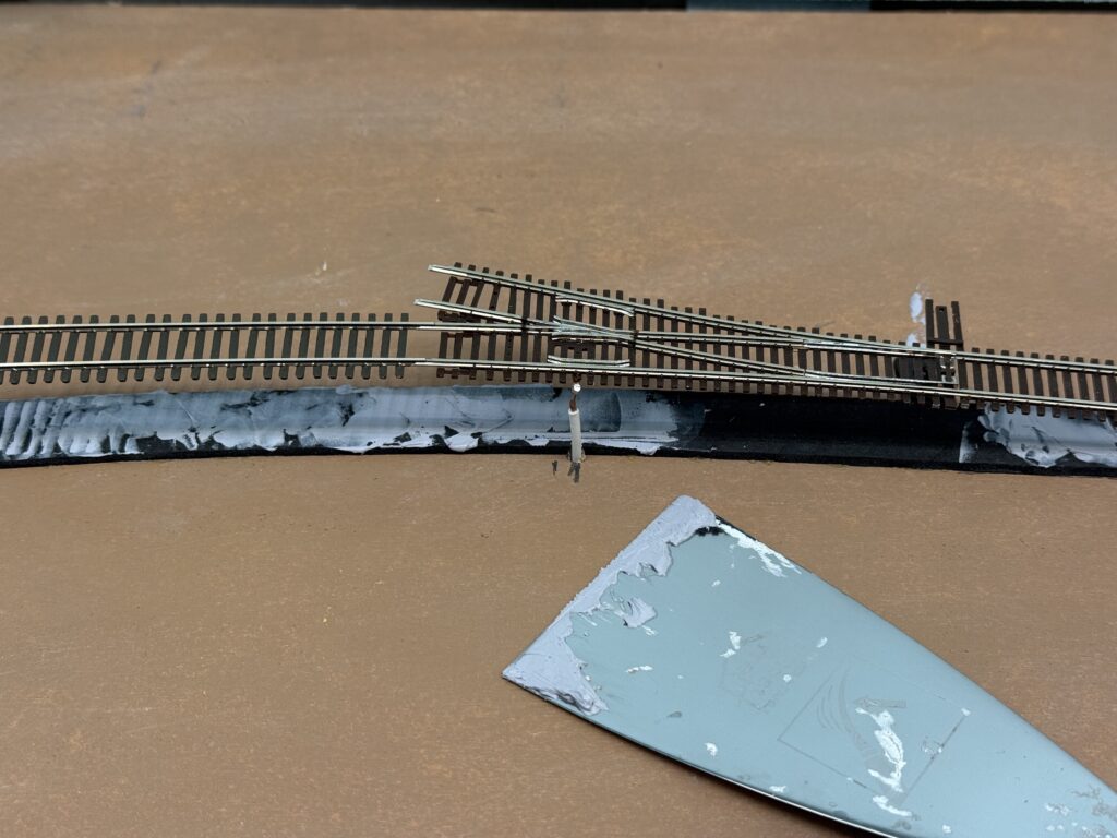
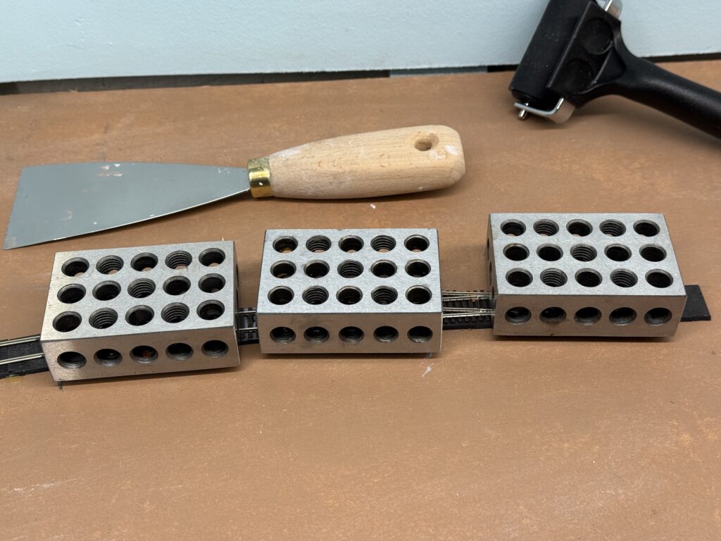
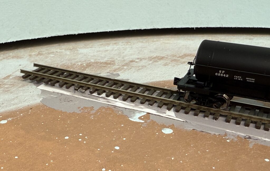
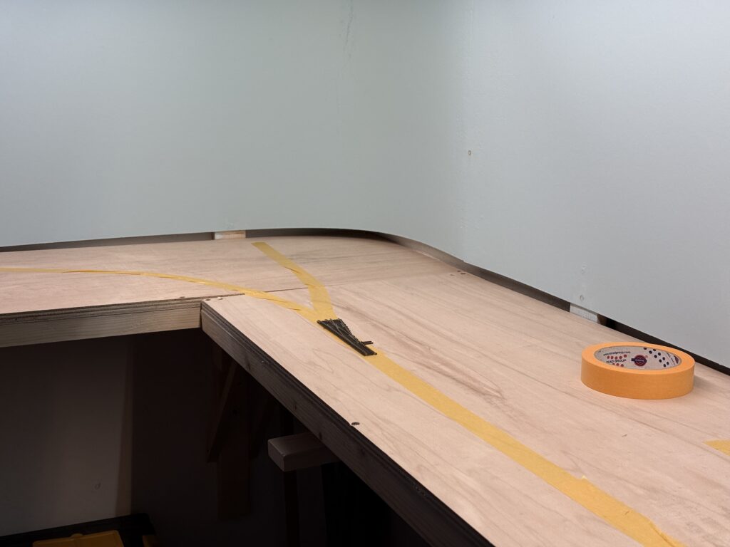
While waiting for the EVA foam roadbed glue to cure, I soldered feeders to the rails using a 15W soldering iron and rosin core flux.

Soldering feeders

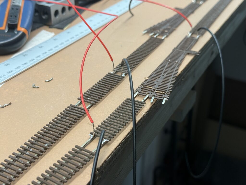
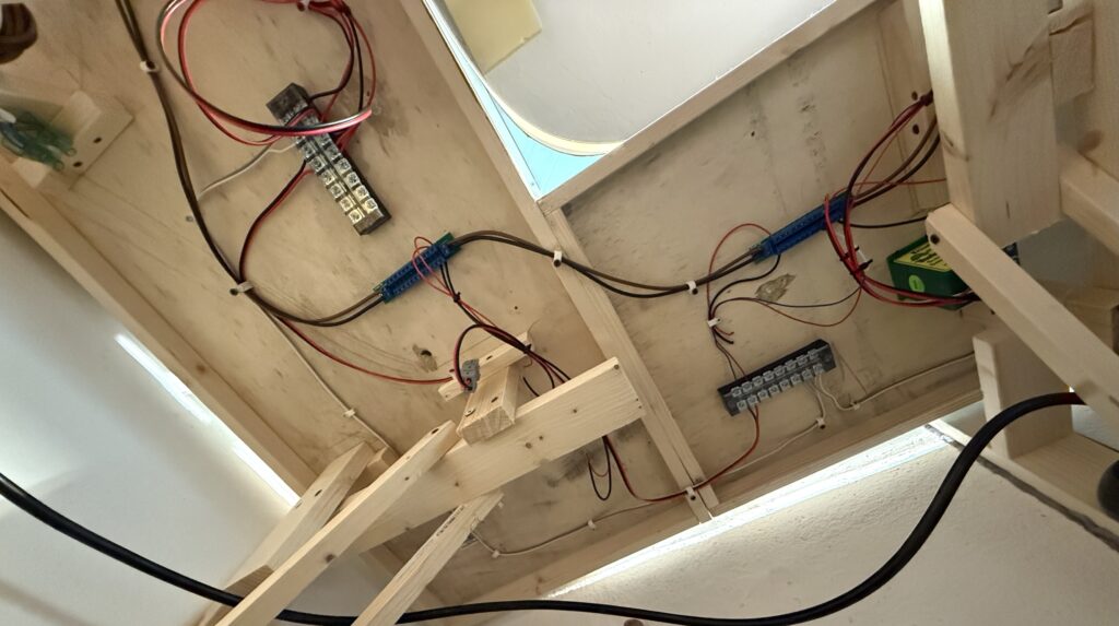
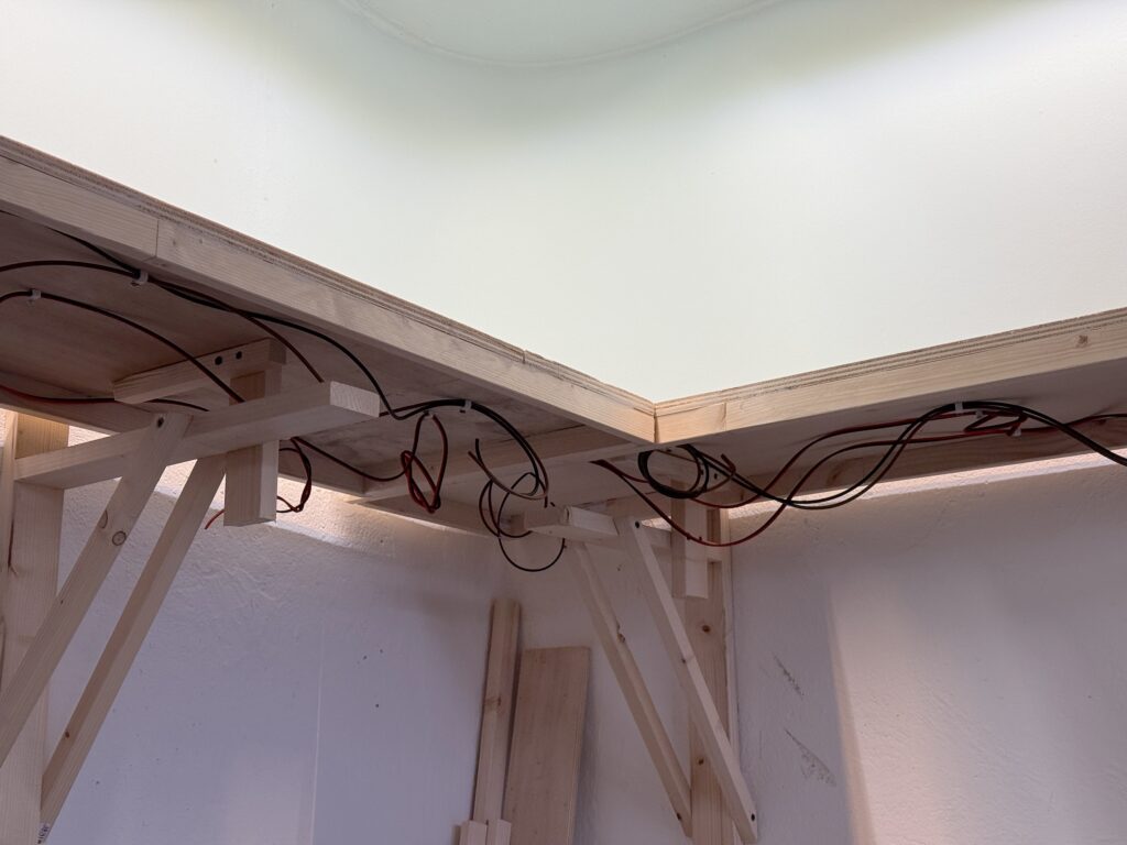
To make wiring easier, I flipped the base upside down. It isn’t screwed to the benchwork yet, so this was simple.

Wiring and Laying Tracks

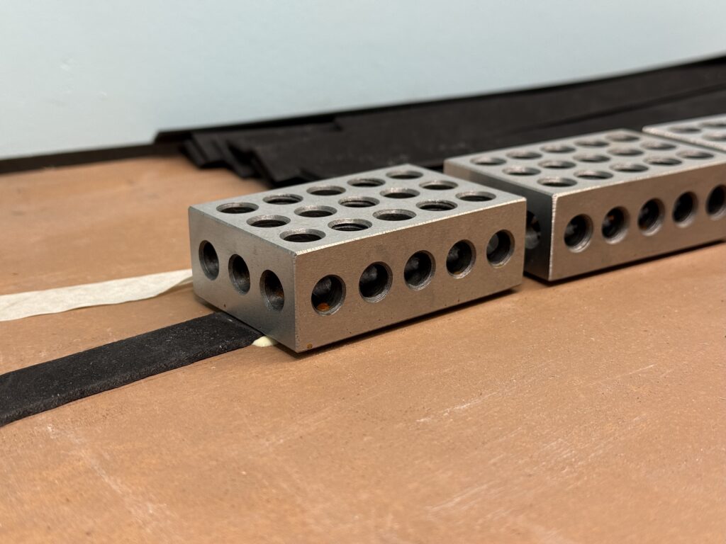
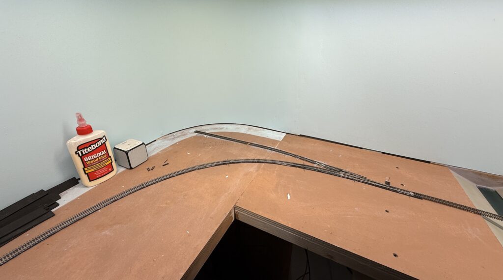
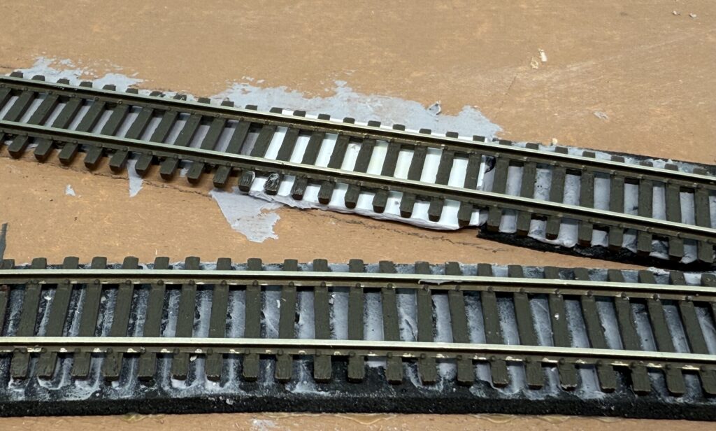
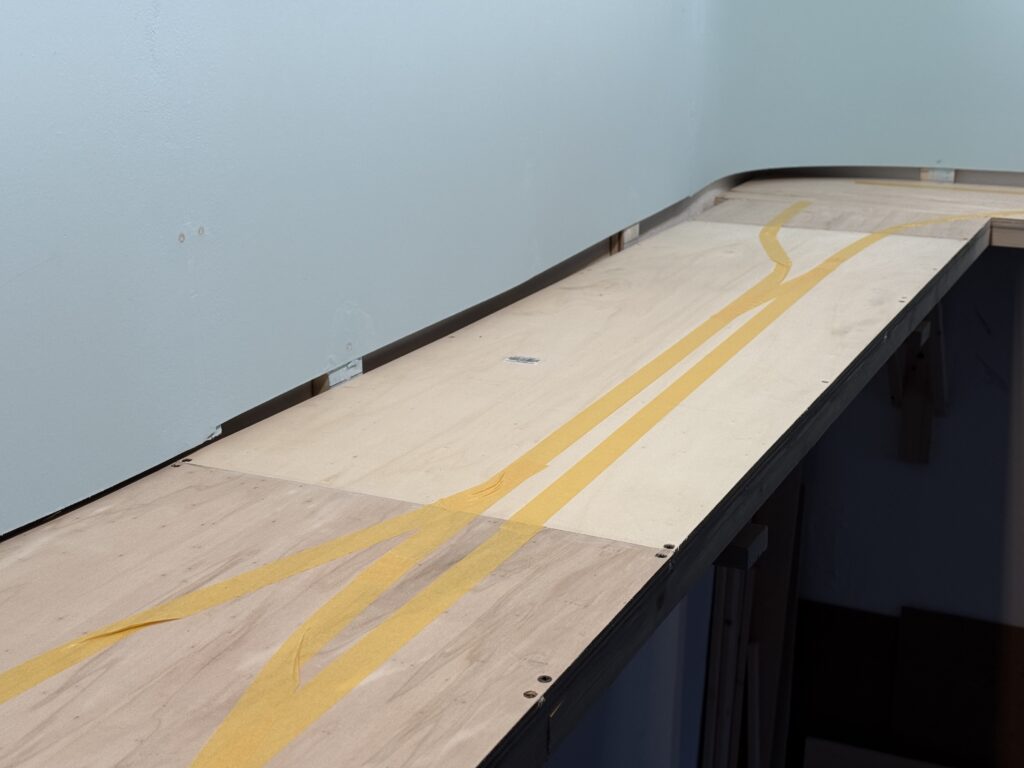
Next, I glued the track to the roadbed using a thin layer of acrylic caulk.

Glueing track with acrylic caulk

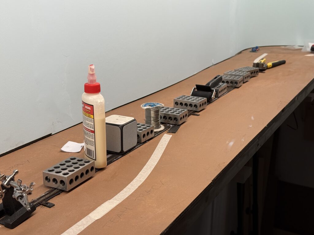
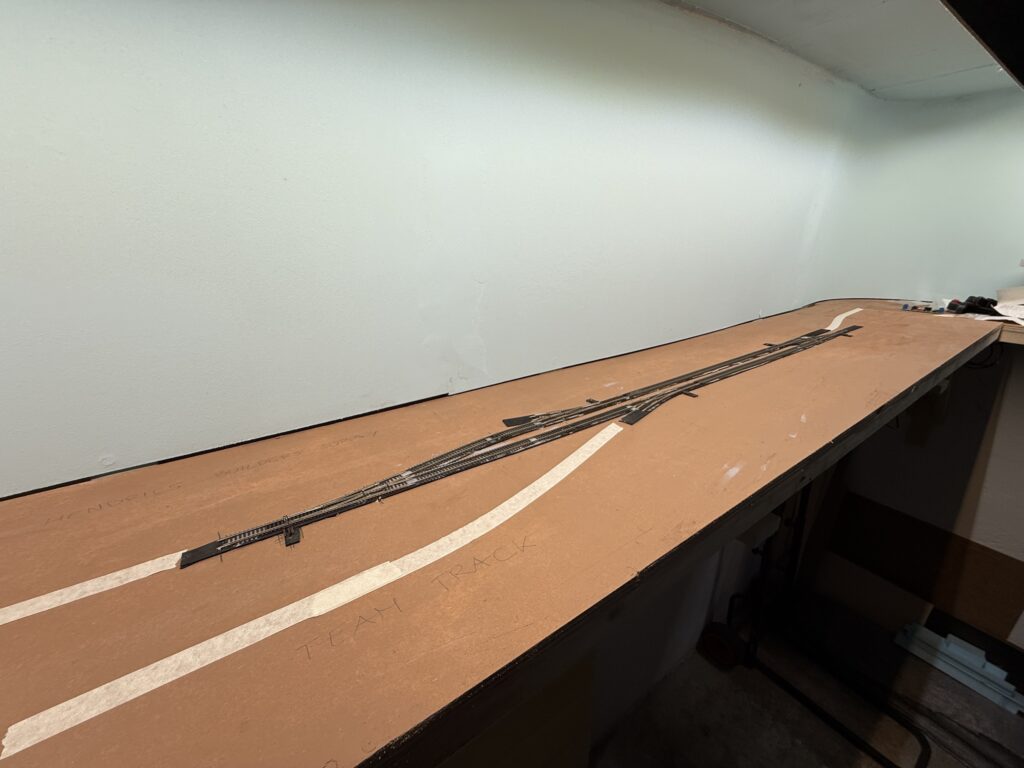
The main line and sidings are now in place. I’ll lay the spurs for Hendrick’s Supply Builders, Oroweat Bakery, and the Team Track next.

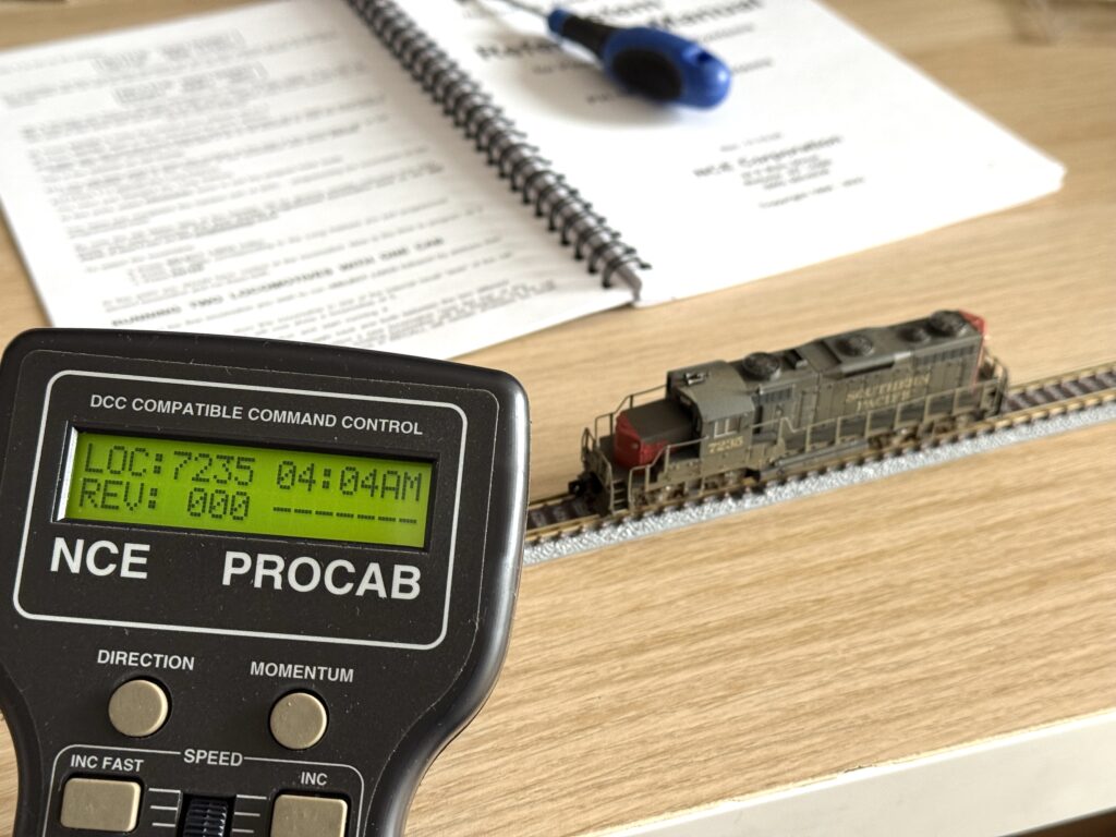
The team track will be wired through a DPDT switch, so it can also serve as a DCC programming track.

Wiring and Laying Tracks: main line and siding.

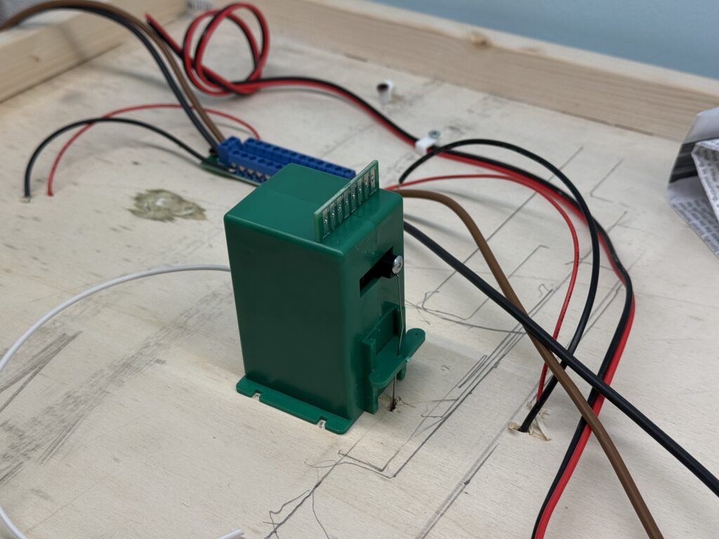
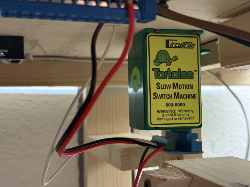
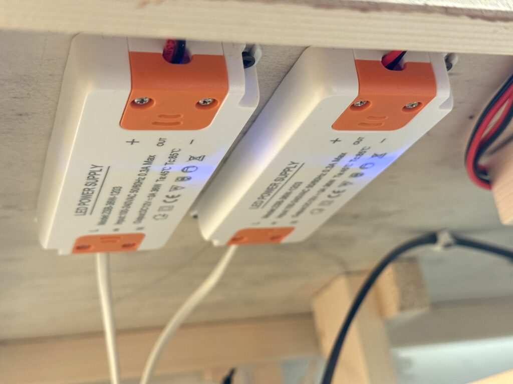
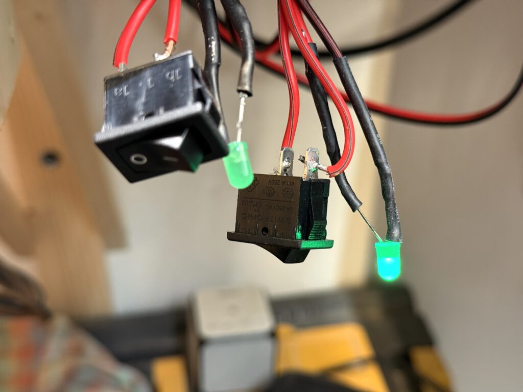
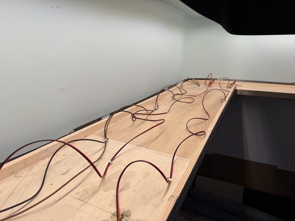
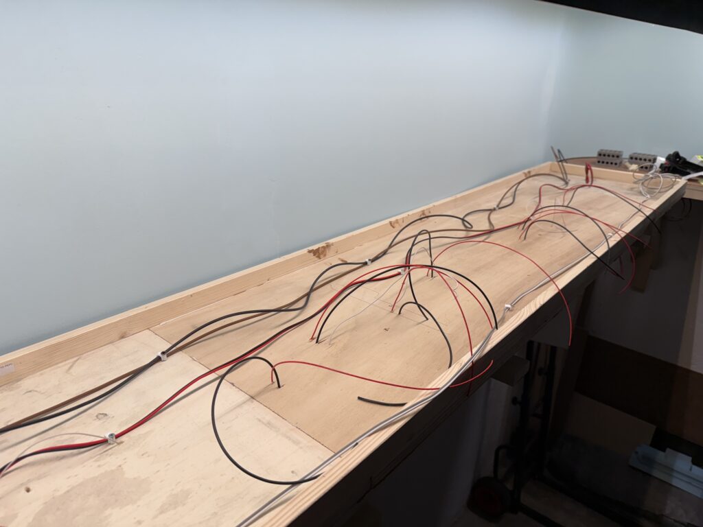
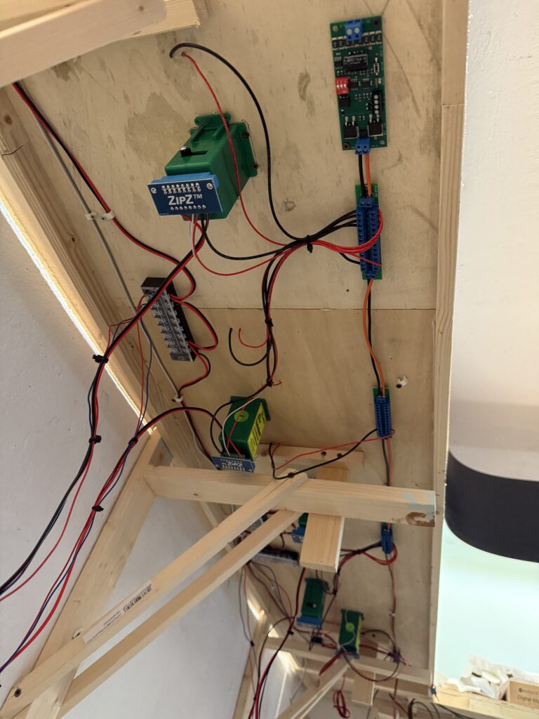
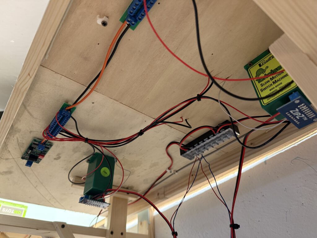
I used terminal strips and cable ties to organize the wiring. The wires hanging under the layout connect to the DPDT switches that control the Tortoise switch machines.

Then, these switches will be mounted on the fascia.

Wiring and laying tracks on a small switching layout requires planning, patience, and flexibility. Each step builds the foundation for smooth operations later on.

Using the right tools and techniques helps avoid frustration and saves time. As the layout grows, keeping things neat and modular makes future changes much easier.

With the basics in place, I’m excited to shift focus to detailing and fine-tuning operations.

Laying Tracks

Laying tracks on my N scale layout

I started laying tracks across most of my N scale layout. When needed, I flipped the plywood base upside down to handle wiring and install the Tortoise switch machines more comfortably.

Roadbed

To start, I used 2mm EVA foam strips for the roadbed. I glued them down with Titebond Original Wood Glue. For simplicity and a prototypical look, I laid the roadbed only under the mainline. Sidings and spurs will go directly onto the plywood.

Laying tracks: EVA foam roadbed
Holding the EVA foam down with metal blocks, while glue dries.

Laying Tracks and Wiring

Next, I soldered 24AWG feeders to the underside of the rails. I drilled holes through the roadbed to connect the feeders to the DCC bus.

Laying tracks: soldering feeders

To secure the track, I applied a thin layer of acrylic caulk using a putty knife. I then placed metal blocks on top to hold the rails in position as the caulk dried.

Using acrylic caulk to glue track down.
Laying Tracks: holding them in place with metal blocks after glueing.

Switch Machines

Once the track was down, I flipped the base again to install the Tortoise switch machines. I also connected the feeders and ran the DCC bus wires.

Installing Tortoise switch machines

Afterward, I inserted the piano wire into the hole in the turnout’s throwbar.

Laying tracks: Atlas Code 55 #5 turnout

I then screwed the switch machine to the plywood base and connected it using ZipZ solderless connectors.

Tortoise switch machine installed

Each Tortoise is controlled by a DPDT toggle switch and powered by a 12V DC supply

Power Supply

I installed two 3A 12V DC power supplies under the layout – one for the switch machines, and the other for layout lighting. This includes LEDs in buildings, vehicles, and streetlights.

Power supplies for Tortoise switch machines and for layout lights

To monitor power delivery, I added a main switch to each 12V output. These switches illuminate an LED when active. I’ll mount both switches and LEDs on the fascia for easy access.

Power supply SPDT switches

Trackwork Fine Tuning

The first section of tracks on my N scale layout is complete. Track has been laid, wiring is done and the first turnout is controlled by a properly installed Tortoise switch machine.

Here is the Conrock and Skyline ready-mix concrete spur.

Track laying: First section of layout is complete
Conrock spur

I used thin pieces of styrene to shim tracks. One for the transition in track height from mainline (photo below, bottom) to the Conrock spur (photo below, top), and another one at the end of the same spur to keep the track level.

Laying tracks: styrene shims

Wiring should be neat and well-organized to make troubleshooting easier if problems occur. Here is how I managed wiring on the Burbank Branch in N scale.

Wiring under the layout

The trackwork phase marks a major milestone in building the layout, which is now coming together with solid progress.

Careful planning now will ensure smoother operations and fewer issues later and sets the foundation for future scenery and detailing.

Trackplan and Wiring

Transfer the trackplan on plywood and start wiring the DCC and DC buses

Trackplan

I used masking tape to transfer the trackplan onto the plywood base, then started wiring the DCC and accessory DC buses.

test-fitting the trackplan using masking tape
Trackplan and wiring: test-fitting using masking tape

What works on paper doesn’t necessarily translate well to the layout. I like to use masking tape to sketch a rough version of the trackplan directly on the plywood subroadbed, allowing me to test-fit curves, sidings and spurs.

Wiring

There are three main buses running under the layout:

  • DCC bus, using 2.5mm² wires (14 AWG)
  • 12VC DC bus for Tortoise switch machines, using 0.75mm² wires (18 AWG)
  • 12VC DC bus for lighting, including streetlights and structure lights, using 0.75mm² wires (18 AWG)

I flipped the plywood base and started fixing the bus wires in a temporary, untidy manner. I will clean up the wiring once all the track feeders and Tortoise switch machines are installed, so that I can determine the correct length for each wire.

Plywood base flipped and wire bus installed
Trackplan and wiring: temporary length bus wires installed.

To tap power without cutting or stripping main wires, I used suitcase connectors – quick, reliable, and ideal for temporary setups. They let me add feeders or accessories on the fly, which is perfect while I’m still fine-tuning the layout.

This approach saves time now and prevents headaches later when the layout is more complete.

Wiring the layout with DCC and accessory power requires both solid planning and a bit of foresight. I installed a robust DCC bus using heavy-gauge wire for consistent power delivery, with feeders soldered in regularly to avoid voltage drops.

Accessory wiring, like 12V DC lines for Tortoise machines and lighting, runs separately for clarity and ease of troubleshooting.

While the system is built to be dependable, I’ve allowed for future adjustments – leaving a bit of slack, labeling connections, and routing wires with accessibility in mind. Layouts evolve, and the wiring can too.

Standards

A set of standards helps in building and operating a reliable model railroad layout

Before starting a model railroad layout construction, a set of standards should be established to ensure smooth operations. These standards apply to trackwork, rolling stock, wiring, and DCC. My bare minimum standards are:

NMRA Standards Gauge N Scale
  • All code 55 tracks, using Micro Engineering flextrack and Atlas turnouts
  • DCC bus and feeders with the appropriate wire gauge
  • All Micro-Trains couplers set at the proper height
  • All BMF-equipped DCC decoders
  • Properly maintained and cleaned rolling stock
  • Properly maintained and cleaned tracks (using white spirits and graphite)

By strictly adhering to these standards, you can ensure smooth operating sessions and, ultimately, an enjoyable and rewarding experience.

NCE DCC Command Station

Digital Command Control for better realistic operations

I opted for the NCE PH5, which is a 5A power booster and DCC command station that includes an NCE Pro Cab, a fascia mounting panel, and an international power supply.

I used a Lenz Compact (easily found in the EU) paired with a few Lokmaus 2 handheld controllers for a long time with my previous layouts 15 years ago. This time, I felt I needed a more advanced command station.

NCE DCC PH5 System

More is more

With advanced consisting, multiple locomotives can be controlled as a single unit, allowing for more realistic train operations on the layout.

The NCE Power Cab supports 4-digit addresses, whereas the Lenz + Lokmaus 2 only support 2-digit addresses. This makes it easier to assign a DCC-equipped locomotive its road number as its DCC address.

Additionally, the Power Cab supports more function keys beyond F4, which is the limit on the Lokmaus 2. With modern sound-equipped locomotives, having access to additional functions is a significant advantage.

I also ordered an additional CAB06p cab, which is what I’ll use normally, while keeping the Pro Cab mainly for programming.

NCE DCC PH5 Control Station and Booster
Controlling a loco (SP GP-20) with NCE ProCab

In comparison to my previous DCC command station (Lenz Compact), the NCE PH5 provides better performance, handling more complex operations with ease.

The fascia mounting panel makes the NCE PH5 easy to integrate into my layout, offering a clean, organized setup.

The NCE PH5’s advanced features give me the flexibility to expand and customize my layout’s operations as needed.